
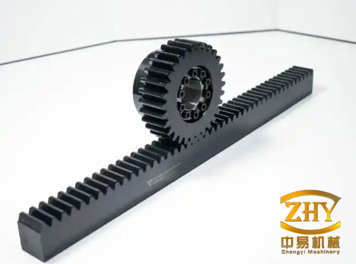
In my design work on heavy machinery, the rack and pinion gear is one of the most direct and robust ways to convert rotary motion into linear motion. The rack and pinion gear is widely used in mining machinery, construction machinery, offshore engineering equipment, metallurgical equipment, and transportation systems. Its appeal is simple: the rack and pinion gear has a direct transmission path, a simple structure, and a high tolerance for severe loading. However, when the rack and pinion gear becomes heavily loaded, the design problem changes significantly. The most dangerous failure mode of a heavy-duty rack and pinion gear is tooth breakage. A broken tooth in a large rack and pinion gear can stop an entire machine, damage adjacent components, and create unsafe conditions. For that reason, I treat bending strength and tooth root stress as primary design drivers for any heavy-duty rack and pinion gear.
Heavy-duty rack and pinion gear transmissions usually adopt a large module and a small number of pinion teeth. For example, in jack-up drilling platform climbing systems, a rack and pinion gear may use a pinion with seven teeth and a module of 80 mm or 100 mm. In large excavator crowd systems, a rack and pinion gear may use a pinion with fourteen teeth and a module of 40 mm or 50 mm. These values are not arbitrary. They are selected to balance load capacity, tooth root strength, manufacturing feasibility, and available space. The problem is that a heavy-duty rack and pinion gear of this size often has no mature design standard and no convenient commercial calculation software. In many projects, I have seen the design process become a slow loop: propose a tooth profile, build a finite element model, calculate the tooth root stress, revise the profile, rebuild the model, and repeat. This is accurate but inefficient. I therefore prefer a design method that combines a special tooth profile design with a fast analytical calculation of tooth root stress for the rack and pinion gear.
The focus of this article is the heavy-duty rack and pinion gear with a large module. I will describe how I select tooth profile parameters, how I determine the critical loading point, and how I calculate tooth root stress quickly. I will also compare the analytical result with finite element analysis for a representative rack and pinion gear used in a jack-up drilling platform. The comparison shows that the fast method is sufficiently accurate for initial design and parameter optimization of a heavy-duty rack and pinion gear.
Failure modes and design priorities for a heavy-duty rack and pinion gear. In an open rack and pinion gear drive, two failure modes dominate: tooth breakage and tooth surface wear. Tooth breakage is sudden and catastrophic. Wear is progressive and reduces transmission accuracy, increases vibration, and eventually changes the load distribution along the rack and pinion gear tooth. For a heavy-duty rack and pinion gear, I therefore prioritize root bending strength and then control wear through pressure angle, tooth thickness, hardness, lubrication, and surface finish. A large module increases the bending section modulus of the rack and pinion gear tooth, but it also increases manufacturing difficulty. A small number of pinion teeth reduces the size of the pinion, but it increases the risk of undercut and root interference. The design must therefore be an integrated compromise.
Why conventional rack and pinion gear manufacturing methods are not always suitable. A large-module rack and pinion gear is not usually produced by ordinary hobbing or shaping. The pinion is often milled according to a specially designed tooth profile. The rack is often numerically cut or cast according to the same profile. In older designs, the rack and pinion gear tooth profile was sometimes approximated by three circular arcs: a root arc below the base circle, one arc between the root arc and the pitch circle, and another arc above the pitch circle. In service, I have seen such a rack and pinion gear produce large transmission errors, vibration, and severe wear. If the root arc is poorly designed, the rack and pinion gear may even suffer tooth breakage. This experience leads me to a more systematic tooth profile design method.
Tooth profile design for a heavy-duty rack and pinion gear. The goal of tooth profile design is to obtain a rack and pinion gear that has sufficient tip thickness, adequate contact ratio, controlled backlash, a favorable root fillet, and a rack tooth shape that matches the pinion. I treat the following parameters as the main variables: module, number of pinion teeth, pressure angle, profile shift coefficient, addendum coefficient, dedendum coefficient, tip clearance, backlash, root fillet radius, and rack effective addendum.
Tip thickness of the pinion in a rack and pinion gear. For an open rack and pinion gear, a thin tooth tip wears quickly. For a rack and pinion gear that carries fatigue loading, I recommend a tip thickness of at least 0.4 times the module. For a rack and pinion gear that mainly carries static loading, such as a jack-up drilling platform climbing drive, a tip thickness of at least 0.15 times the module can be acceptable. In some large excavator crowd rack and pinion gear drives, the pinion tip thickness has been about 0.41 to 0.42 times the module. In some offshore jack-up rack and pinion gear climbing drives, the tip thickness has been about 0.14 to 0.15 times the module. These values show how the duty cycle changes the design rule.
The tip thickness of the pinion in a rack and pinion gear can be calculated from the following relationship:
$$S_a = d_a \left( \frac{\pi}{2z} + \frac{2x\tan\alpha}{z} + \operatorname{inv}\alpha – \operatorname{inv}\alpha_a \right)$$
where \(S_a\) is the tip thickness, \(d_a\) is the tip diameter, \(z\) is the number of pinion teeth, \(x\) is the profile shift coefficient, \(\alpha\) is the reference pressure angle, and \(\alpha_a\) is the pressure angle at the tip diameter. The tip pressure angle is obtained from:
$$\cos\alpha_a = \frac{d_b}{d_a}$$
where \(d_b\) is the base diameter of the pinion. In my design procedure for a rack and pinion gear, I first select a target tip thickness based on the load type, then use these equations to check whether the chosen module, tooth number, pressure angle, and profile shift produce an acceptable tip. If the tip is too thin, I increase the profile shift, increase the module, or change the pressure angle. If the tip is too thick, I may reduce the profile shift or adjust the addendum.
| Duty type for rack and pinion gear | Recommended minimum tip thickness | Typical application |
|---|---|---|
| Fatigue-loaded open rack and pinion gear | \(S_a \ge 0.4m\) | Large excavator crowd drive, continuous mining drive |
| Static-loaded rack and pinion gear | \(S_a \ge 0.15m\) | Jack-up drilling platform climbing drive |
| Observed heavy excavator practice | \(S_a \approx 0.41m\) to \(0.42m\) | Large mining excavator rack and pinion gear |
| Observed offshore practice | \(S_a \approx 0.14m\) to \(0.15m\) | Jack-up drilling platform climbing rack and pinion gear |
Contact ratio of a heavy-duty rack and pinion gear. Contact ratio, also called overlap ratio, determines how smoothly the load transfers from one tooth pair to the next in a rack and pinion gear. If the contact ratio is too small, the rack and pinion gear experiences high impact, noise, and unfavorable load distribution. For a fatigue-loaded rack and pinion gear, I recommend a contact ratio of at least 1.2. For a static-loaded rack and pinion gear, such as a jack-up climbing system, a contact ratio of at least 1.05 can be sufficient. Many static rack and pinion gear drives use a pressure angle greater than 25 degrees, which increases the contact ratio. If the pressure angle is too high and the addendum is too large, the pinion tip may become pointed or nearly pointed, which creates plastic deformation risk.
The contact ratio of a rack and pinion gear can be estimated from:
$$\varepsilon = \frac{z_1(\tan\alpha_{a1} – \tan\alpha)}{2\pi} + \frac{2h’_{a2}}{\pi m \sin 2\alpha}$$
where \(z_1\) is the number of pinion teeth, \(\alpha_{a1}\) is the tip pressure angle of the pinion, \(h’_{a2}\) is the effective addendum of the rack above the meshing point, and \(m\) is the module. This equation is especially useful when I am adjusting the rack addendum and the pinion profile shift in a heavy-duty rack and pinion gear. The effective rack addendum is not the same as the total rack tooth height. It is the portion of the rack tooth that participates in meshing above the lowest point of contact.
| Load condition for rack and pinion gear | Recommended contact ratio | Design consequence |
|---|---|---|
| Fatigue loading | \(\varepsilon \ge 1.2\) | Lower impact and better load sharing |
| Static loading | \(\varepsilon \ge 1.05\) | Acceptable for high-pressure-angle rack and pinion gear |
| Very high pressure angle | Check tip thickness | Avoid pointed or weak pinion tip |
| Low precision rack and pinion gear | Assume single-tooth contact | Root stress may be controlled by tip loading |
Backlash and clearance in a heavy-duty rack and pinion gear. Backlash is necessary in a rack and pinion gear because of manufacturing error, center distance variation, cumulative pitch error, and thermal expansion caused by friction. For an open rack and pinion gear, I usually choose a circumferential backlash of about 0.12 to 0.15 times the module. I obtain this backlash by reducing the tooth thickness of the pinion and the rack. The rack root thickness is usually larger than the pinion root thickness, which is favorable because the rack often has a stiffer body. In a rack and pinion gear, backlash must be large enough to prevent binding but not so large that impact and wear increase.
Tip clearance is also important. In a heavy-duty rack and pinion gear, the tip clearance can be used as a lubricant reservoir. For open gearing, I often select a tip clearance of about 10 mm to 12 mm. This space helps retain grease or oil and reduces the chance of metal-to-metal contact at the tip. The rack tooth height relationship can be written as:
$$h_{a2} = h_{f1} – c^* m$$
where \(h_{a2}\) is the rack addendum, \(h_{f1}\) is the pinion dedendum, and \(c^*\) is the clearance coefficient. The exact value depends on the required lubricant volume and the allowable loss of contact ratio.
Root fillet design for the pinion in a rack and pinion gear. The root fillet is one of the most important features for bending strength. A single circular root fillet is generally better than a double circular root fillet for lowering stress concentration in the pinion. However, increasing the root fillet radius can cause meshing interference. The correct approach is to keep the effective involute portion and then enlarge the root fillet as much as possible without interfering with the mating rack. For a rack and pinion gear, the lowest meshing point is usually at or slightly above the base circle. In many designs, it is about 2 mm to 3 mm above the base circle.
I set the tangent point between the root fillet and the involute at the lowest meshing point. The root fillet radius is then calculated from:
$$r_\rho = \frac{D_b}{2} \left[ \tan\left(\alpha_{ce} + \operatorname{inv}\alpha_{ce} + \frac{\pi}{z} – \frac{S_{\min}}{D} – \operatorname{inv}\alpha\right) – \tan\alpha_{ce} \right]$$
and the pressure angle at the tangent point is:
$$\alpha_{ce} = \arccos\left(\frac{D_b}{D_{ce}}\right)$$
where \(D_b\) is the base diameter, \(D_{ce}\) is the diameter at the tangent point between the root fillet and the involute, \(S_{\min}\) is the actual tooth thickness at the reference diameter, and \(D\) is the reference diameter. For a heavy-duty rack and pinion gear, I typically take:
$$D_{ce} = D_b + (2 \text{ to } 3)\,\text{mm}$$
This small offset ensures that the involute remains effective while allowing a larger root fillet. A larger root fillet reduces the stress concentration in the pinion of the rack and pinion gear. However, I always check the fillet against the rack tip to avoid interference.
| Root feature for rack and pinion gear | Preferred choice | Reason |
|---|---|---|
| Pinion root fillet | Single circular arc | Lower stress concentration than double arc |
| Rack root fillet | Double circular arc if needed | Reduces rack root height and increases rack body stiffness |
| Tangent point | At or just above base circle | Maintains effective involute and allows larger fillet |
| Offset above base circle | 2 mm to 3 mm | Practical compromise for large module rack and pinion gear |
Rack tooth profile in a heavy-duty rack and pinion gear. In a rack and pinion gear, the pitch point always lies on the pinion reference circle, regardless of whether the mounting distance is standard. This fact simplifies the rack geometry. The effective addendum of the rack above the meshing point is:
$$h’_{a2} = r – r_{ce}\cos(\alpha – \alpha_{ce})$$
The effective tooth height of the rack is:
$$h_{a2e} = h’_{a2} + x m$$
and the total rack tooth height is related to the pinion dedendum by:
$$h_{a2} = h_{f1} – c^* m$$
These equations allow me to match the rack tooth to the pinion tooth in a rack and pinion gear. The rack tooth should be thick at the root and should not have a sharp tip. Because the rack is often longer and heavier than the pinion, its root stress is usually lower, but the rack can still deform if the root height is excessive. A double circular root fillet can reduce the rack root height and increase the stiffness of the rack body.
Load distribution in a heavy-duty rack and pinion gear. The critical question in root stress calculation is whether the maximum stress occurs at the single-tooth contact point or at the tip contact point. In a high-precision rack and pinion gear, the load may be shared between two tooth pairs, and the critical stress may occur near the single-tooth contact point. In a low-precision heavy-duty rack and pinion gear, the load distribution is much worse. Even if the theoretical contact ratio is greater than 1.2, manufacturing errors and deflections can cause one tooth pair to carry most or all of the load. In that case, the root stress must be calculated as if the full load acts at the tooth tip. This is the condition I use for large-module rack and pinion gear drives in mining and offshore equipment.
The load distribution factor can be estimated from:
$$K_a = \frac{\varepsilon}{2}\left(0.9 + \frac{0.4 C_r \Delta}{F_{teff}/b}\right)$$
where \(C_r\) is the average mesh stiffness of two meshing tooth pairs, \(\Delta\) is the base pitch difference, \(\varepsilon\) is the contact ratio, \(F_{teff}\) is the effective tangential force at the reference circle, and \(b\) is the face width. The effective tangential force includes the application factor, dynamic factor, and face load factor:
$$F_{teff} = F_t K_A K_v K_B$$
When \(K_a \le 1\), the single-tooth contact point may be the most severe. When \(K_a \ge 1\), the entire load is assumed to act at the tooth tip. For a heavy-duty rack and pinion gear with low precision, \(K_a\) is often greater than 1, so I use tip loading for root stress. This is a conservative but realistic assumption for an open rack and pinion gear.
| Load distribution condition | Value of \(K_a\) | Critical loading point for rack and pinion gear |
|---|---|---|
| High-precision rack and pinion gear | \(K_a \le 1\) | Single-tooth contact point |
| Low-precision rack and pinion gear | \(K_a \ge 1\) | Tooth tip |
| Heavy-duty open rack and pinion gear | Usually \(K_a \ge 1\) | Tooth tip with full load |
| Static offshore rack and pinion gear | Often \(K_a \ge 1\) | Tooth tip, compare with yield strength |
Tooth root stress calculation for a rack and pinion gear. For a large-module rack and pinion gear, I use the ISO 30-degree tangent method to define the critical root section. This method is simple and has been shown to agree with more complex folded-section methods within about 5 to 6 percent. The nominal tooth root stress is:
$$\sigma_{F0} = \frac{F_n \cos\delta_a}{b m} Y_{Fa} Y_{Sa}$$
where \(F_n\) is the normal load, \(\delta_a\) is the load angle, \(b\) is the face width, \(m\) is the module, \(Y_{Fa}\) is the form factor, and \(Y_{Sa}\) is the stress concentration factor. The form factor is:
$$Y_{Fa} = \frac{6 (h_F/m)\cos\delta_a}{(S_F/m)^2 \csc\alpha}$$
and the stress concentration factor can be written as:
$$Y_{Sa} = \frac{(1.2 + 0.13 L_a) q_s}{\sqrt{1.21 + 2.3/L_a}}$$
where \(S_F\) is the critical root thickness, \(h_F\) is the bending moment arm, \(L_a\) is a fillet parameter, and \(q_s\) is a notch sensitivity factor. The two critical geometric parameters are \(S_F\) and \(h_F\). I calculate them separately for the pinion and the rack.
Pinion critical section in a rack and pinion gear. For the pinion, the critical root thickness and moment arm are:
$$S_F = 2(r_f + r_\rho)\sin\frac{\pi}{z} – 2r_\rho \cos 30^\circ$$
$$h_F = \frac{r_b}{\cos\delta_a} – (r_f + r_\rho)\cos\frac{\pi}{z} + r_\rho \sin 30^\circ$$
where \(r_f\) is the root circle radius, \(r_\rho\) is the root fillet radius, \(r_b\) is the base radius, and \(z\) is the number of pinion teeth. These equations are derived from the geometry of the 30-degree tangent line and the root fillet circle. They are convenient for a heavy-duty rack and pinion gear because they directly show the influence of root fillet radius and profile shift through the root circle radius.
Rack critical section in a rack and pinion gear. For the rack, the critical root thickness and moment arm are:
$$S_F = \pi m – 2r_\rho \cos 30^\circ – e$$
$$h_F = h – h_{11} – h_{22} = h – \frac{S_a}{2}\tan\alpha – r_\rho(1-\sin 30^\circ)$$
where \(e\) is the distance between the centers of two adjacent root fillets, \(h\) is the effective rack height, and \(S_a\) is the rack tooth thickness at the effective height. If the rack uses a single root arc, \(e=0\). If the rack uses a double root arc, \(e\) is the distance between the two arc centers. In a rack and pinion gear, the rack tooth often has a larger root thickness than the pinion, so the rack root stress is usually lower. However, the rack can still fail if the root fillet is too small or if the rack body is not stiff enough.
Load angle in a rack and pinion gear. The load angle \(\delta_a\) defines the direction of the normal force relative to the tooth centerline. For a rack and pinion gear, it can be calculated from:
$$\delta_a = \psi – \theta – \operatorname{inv}\alpha$$
where:
$$\theta = \frac{1}{z}\left(\frac{\pi}{2} + 2x\tan\alpha\right)$$
and:
$$\psi = \sqrt{\left(\frac{r_a}{r_b}\right)^2 – 1}$$
Therefore:
$$\delta_a = \sqrt{\left(\frac{r_a}{r_b}\right)^2 – 1} – \frac{1}{z}\left(\frac{\pi}{2} + 2x\tan\alpha\right) – \operatorname{inv}\alpha$$
This load angle is used in both the form factor and the moment arm. A small change in profile shift or pressure angle changes \(\delta_a\), which changes the bending moment arm and the root stress. In my experience with a heavy-duty rack and pinion gear, the load angle is one of the most sensitive parameters in the analytical stress calculation.
| Symbol | Meaning in rack and pinion gear design | Typical unit |
|---|---|---|
| \(m\) | Module | mm |
| \(z\) | Number of pinion teeth | – |
| \(x\) | Profile shift coefficient | – |
| \(\alpha\) | Reference pressure angle | degree or rad |
| \(\varepsilon\) | Contact ratio | – |
| \(S_a\) | Tip thickness | mm |
| \(r_\rho\) | Root fillet radius | mm |
| \(S_F\) | Critical root thickness | mm |
| \(h_F\) | Bending moment arm | mm |
| \(\delta_a\) | Load angle | rad |
| \(\sigma_{F0}\) | Nominal tooth root stress | MPa |
Worked example for a jack-up drilling platform rack and pinion gear. I now apply the method to a heavy-duty rack and pinion gear used in a jack-up drilling platform climbing system. The pinion has a module of 80 mm, seven teeth, a reference diameter of 560 mm, a profile shift coefficient of 0.28, and a pressure angle of 30 degrees. The pinion face width is 190 mm, the rack face width is 177 mm, and the design thrust is 2000 kN. This is a static-loaded rack and pinion gear, so I allow a smaller tip thickness than I would for a fatigue-loaded open rack and pinion gear. The calculated root fillet radius is 35 mm, and the tip thickness is about 0.15 times the module.
| Parameter | Value for the example rack and pinion gear |
|---|---|
| Normal module \(m\) | 80 mm |
| Number of pinion teeth \(z\) | 7 |
| Reference diameter \(d\) | 560 mm |
| Profile shift coefficient \(x\) | 0.28 |
| Pressure angle \(\alpha\) | 30 degrees |
| Pinion face width | 190 mm |
| Rack face width | 177 mm |
| Design thrust | 2000 kN |
| Pinion root fillet radius | 35 mm |
| Tip thickness target | 0.15m |
Using the analytical method, I calculate the pinion root stress and the rack root stress. I then compare these values with a finite element analysis of the same rack and pinion gear. The finite element model includes one pair of meshing teeth. The thrust is applied to the rack, and the tooth root stress is evaluated for the engaging and disengaging positions. The results are summarized in the following table.
| Component in rack and pinion gear | Analytical root stress | Finite element root stress | Difference |
|---|---|---|---|
| Pinion root | 514 MPa | 501 MPa | 2.5 percent |
| Rack root | 574 MPa | 546 MPa | 5.1 percent |
The maximum difference between the analytical method and the finite element analysis is about 5.1 percent. For a heavy-duty rack and pinion gear, this is acceptable for initial design. The analytical method is much faster than building a finite element model for every parameter change. I can use it to screen module, tooth number, pressure angle, profile shift, and root fillet radius before performing a detailed finite element analysis. This makes the design of a heavy-duty rack and pinion gear more efficient and more systematic.
Design sensitivity of a heavy-duty rack and pinion gear. In my experience, the following trends are important when optimizing a rack and pinion gear. Increasing the module increases the tooth size and reduces root stress, but it also increases weight and manufacturing cost. Increasing the number of pinion teeth improves contact ratio and reduces undercut risk, but it increases the pinion diameter. Increasing the pressure angle increases tooth root thickness and contact ratio, but it also increases radial force and may reduce tip thickness. Increasing positive profile shift increases pinion tooth thickness and bending strength, but it reduces rack tooth thickness at the mesh and can increase the risk of interference if the root fillet is too large. Increasing the root fillet radius reduces stress concentration, but it can cause interference with the rack tip. For a rack and pinion gear, the best design is usually found by balancing these effects rather than maximizing any single parameter.
| Change in rack and pinion gear parameter | Effect on root stress | Effect on contact ratio | Effect on tip thickness | Main risk |
|---|---|---|---|---|
| Increase module | Decrease | Slight decrease | Increase | Higher weight and cost |
| Increase pinion teeth | Decrease | Increase | Increase | Larger pinion envelope |
| Increase pressure angle | Decrease | Increase | Decrease | Higher radial load |
| Increase positive profile shift | Decrease for pinion | Depends on tip | Decrease | Rack interference |
| Increase root fillet radius | Decrease | No direct change | No direct change | Meshing interference |
| Increase backlash | No direct change | Slight decrease | No direct change | Impact and noise |
Manufacturing and inspection considerations for a heavy-duty rack and pinion gear. The analytical design is only useful if the rack and pinion gear can be manufactured and inspected. For a large-module rack and pinion gear, I specify the tooth profile on the drawing with sufficient geometric data: module, number of teeth, pressure angle, profile shift, tip diameter, root diameter, root fillet radius, tip thickness, and rack effective addendum. The pinion is often milled with a form cutter or generated by a special process. The rack is often flame-cut, plasma-cut, or cast, then machined on the tooth flanks. After heat treatment, I check tooth thickness, root fillet, and surface hardness. For a heavy-duty rack and pinion gear, the root fillet is especially important because it controls the bending fatigue life. I therefore require a smooth fillet without machining marks, cracks, or undercuts.
Inspection of a rack and pinion gear should include pitch deviation, tooth thickness, profile deviation, and root fillet radius. For a static-loaded rack and pinion gear, the inspection can focus on root thickness and fillet quality. For a fatigue-loaded rack and pinion gear, the inspection should also include surface roughness and residual stress. Shot peening or rolling of the root fillet can improve the bending strength of the rack and pinion gear. However, any surface treatment must not damage the involute portion or change the effective tooth thickness beyond the design tolerance.
Load capacity check for a heavy-duty rack and pinion gear. After calculating the root stress, I compare it with the allowable stress of the material. For a static-loaded rack and pinion gear, the comparison is usually made with the yield strength. For a fatigue-loaded rack and pinion gear, the comparison is made with the bending fatigue limit, including the size factor, surface factor, reliability factor, and notch factor. In a heavy-duty rack and pinion gear, the root stress is often high, so I prefer a material with high hardenability and good toughness. The pinion and rack may use different materials because the pinion usually has more load cycles than the rack. The rack can be made from a lower-cost material if the stress is lower, but the rack tooth must still be strong enough to avoid plastic deformation under peak load.
| Design check for rack and pinion gear | Static-loaded rack and pinion gear | Fatigue-loaded rack and pinion gear |
|---|---|---|
| Primary comparison | Root stress vs yield strength | Root stress vs fatigue limit |
| Critical loading point | Often tooth tip | Single-tooth or tip depending on \(K_a\) |
| Tip thickness rule | \(S_a \ge 0.15m\) | \(S_a \ge 0.4m\) |
| Contact ratio rule | \(\varepsilon \ge 1.05\) | \(\varepsilon \ge 1.2\) |
| Root fillet | Single arc, as large as possible | Single arc, smooth and peened if needed |
| Backlash | 0.12m to 0.15m | 0.12m to 0.15m |
Why the fast method is useful for a rack and pinion gear. The finite element method is accurate, but it is not convenient for the early stages of design. A heavy-duty rack and pinion gear may require dozens of iterations before a feasible profile is found. Each finite element model requires geometry creation, meshing, contact definition, load application, and post-processing. The analytical method presented here reduces the iteration time dramatically. I can calculate the tip thickness, contact ratio, root fillet radius, load angle, critical root thickness, moment arm, and root stress in a spreadsheet. The finite element method is then used only for final verification. This combination is efficient and reliable for a heavy-duty rack and pinion gear.
Another advantage of the analytical method is that it shows the influence of each parameter directly. For example, if the pinion root stress is too high, I can see whether increasing the profile shift, increasing the root fillet radius, or increasing the module will produce the required reduction. If the contact ratio is too low, I can adjust the rack addendum or the pressure angle. This transparency is valuable when designing a rack and pinion gear for a new machine because the boundary conditions are often not fully known at the beginning.
Summary of the design workflow for a heavy-duty rack and pinion gear. My workflow for a heavy-duty rack and pinion gear is as follows. First, I define the application: static or fatigue, load magnitude, speed, life, environment, and space envelope. Second, I select the module and number of pinion teeth based on load and experience. For a jack-up climbing rack and pinion gear, this may be seven teeth and a module of 80 mm or 100 mm. For a large excavator crowd rack and pinion gear, this may be fourteen teeth and a module of 40 mm or 50 mm. Third, I select the pressure angle and profile shift. Fourth, I calculate tip thickness and adjust the profile shift or addendum. Fifth, I calculate contact ratio and adjust the rack effective addendum. Sixth, I determine backlash and tip clearance. Seventh, I calculate the root fillet radius and check interference. Eighth, I calculate the load distribution factor and decide whether to use single-tooth or tip loading. Ninth, I calculate the root stress for the pinion and rack. Tenth, I compare the results with allowable stress and, if necessary, iterate. Finally, I verify the design with finite element analysis.
| Step | Action for rack and pinion gear | Key output |
|---|---|---|
| 1 | Define duty and envelope | Load, speed, life, space |
| 2 | Select module and tooth number | \(m\), \(z\) |
| 3 | Select pressure angle and profile shift | \(\alpha\), \(x\) |
| 4 | Check tip thickness | \(S_a\) |
| 5 | Check contact ratio | \(\varepsilon\) |
| 6 | Set backlash and clearance | Backlash, \(c^*\) |
| 7 | Calculate root fillet | \(r_\rho\) |
| 8 | Calculate load distribution | \(K_a\) |
| 9 | Calculate root stress | \(\sigma_{F0}\) for pinion and rack |
| 10 | Compare with allowable stress | Accept or iterate |
| 11 | Verify with finite element analysis | Final confirmation |
Final observations on rack and pinion gear design. The rack and pinion gear is a robust transmission, but a heavy-duty rack and pinion gear requires careful attention to tooth profile and root stress. The design cannot rely only on standard gear formulas because the module is large, the number of pinion teeth is small, and the manufacturing precision is limited. In my work, I have found that a special tooth profile with a large root fillet, adequate tip thickness, controlled backlash, and a properly matched rack addendum gives the best performance. The load distribution factor is essential because it determines whether the root stress should be calculated at the single-tooth contact point or at the tooth tip. For low-precision heavy-duty rack and pinion gear drives, tip loading is the realistic assumption. The analytical root stress method based on the ISO 30-degree tangent line is fast and sufficiently accurate. In the example presented here, the maximum difference from finite element analysis was about 5.1 percent. This makes the method suitable for initial design and parameter optimization of a heavy-duty rack and pinion gear.
When I apply this method to a new rack and pinion gear, I always remember that the result is only as good as the input parameters. The module, tooth number, pressure angle, profile shift, root fillet radius, backlash, and rack effective addendum must be selected with the manufacturing process in mind. A rack and pinion gear that is excellent on paper but impossible to machine or inspect is not a successful design. Therefore, I combine the analytical calculation with practical limits: maximum root fillet radius before interference, minimum tip thickness before wear or plastic deformation, minimum contact ratio before impact, and maximum backlash before noise. The final design is the best compromise among strength, durability, manufacturability, and cost. With this approach, the heavy-duty rack and pinion gear can be designed with confidence and verified efficiently.