
In my research, I focused on the lifting device of a rack and pinion drilling rig because this subsystem controls both the vertical motion of the top drive and the transmission of the drilling load. Unlike a conventional drawworks-based hoisting system, the rack and pinion lifting device uses fixed racks and rotating pinions to convert motor torque into linear motion. This conversion gives the rig active push-down capability, accurate string positioning, and a compact modular arrangement. Because the rack and pinion gears operate under low-speed, heavy-load, and time-varying conditions, I designed a series of static and dynamic experiments to evaluate strength, load sharing, and motion synchronization. I also built corresponding numerical models so that the experimental trends could be interpreted and extended to working conditions that were difficult to reproduce directly.
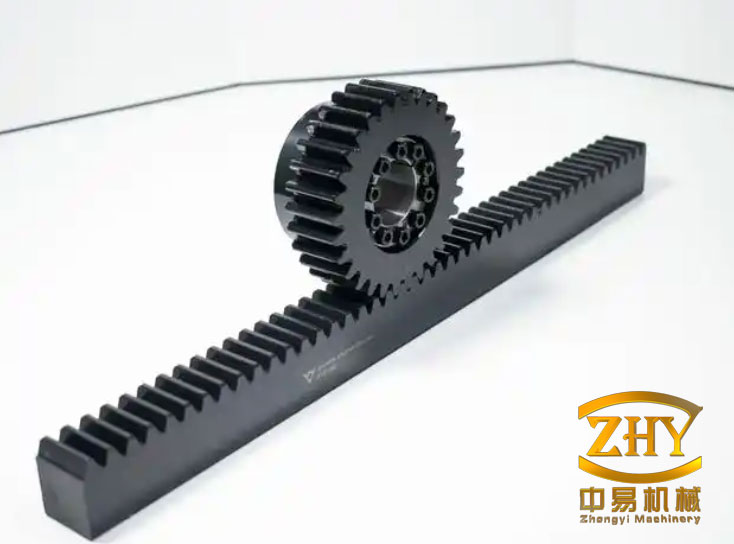
The core mechanical interaction in the lifting device is the meshing behavior of multiple rack and pinion gears. Each pinion is mounted on the lifting box, while each rack is fixed to the derrick. When the motors rotate the pinions, the racks remain stationary and the lifting box translates along the derrick. Therefore, the rack and pinion gears are not merely transmission components; they are the primary load-bearing interfaces between the moving top drive assembly and the fixed derrick structure. I treated the rack and pinion gears as the central object of my static strength analysis, dynamic response analysis, and experimental verification.
From the viewpoint of system composition, the rig can be divided into the derrick, the top drive and lifting device, the wellhead mechanized operation system, the drill floor, and the power catwalk system. Among these, the lifting device is the most critical for hoisting and pushing. I considered a lifting box that carries eight pinions, with four pinions on each side of the box. The racks are installed in sections along the derrick, and each rack is fixed by bolts. The pinions are driven by hydraulic motors through reducers. When the pinions rotate, the lifting box moves upward or downward together with the top drive and the connected pipe string.
I selected a configuration in which the rack and pinion gears are arranged in a centered manner rather than an offset manner. Earlier offset arrangements produced additional bending moments and excessive contact stress. A centered eight-pinion arrangement distributes the load more evenly and reduces the risk of local overload. The design parameters of the rack and pinion gears are summarized in Table 1. These values were used consistently in my theoretical calculations, finite element simulations, and experimental planning.
| Parameter | Pinion | Rack |
|---|---|---|
| Module, $$m$$ (mm) | 20 | 20 |
| Number of teeth, $$Z$$ | 17 | Not applicable |
| Pressure angle, $$\alpha$$ (degree) | 20 | 20 |
| Addendum coefficient, $$h_a^*$$ | 1 | 1 |
| Clearance coefficient, $$c^*$$ | 0.25 | 0.25 |
| Face width, $$b$$ (mm) | 120 | 140 |
| Single rack length, $$L$$ (mm) | Not applicable | 3015 |
| Pitch diameter, $$d$$ (mm) | 340 | Not applicable |
The material properties also influenced the experimental design. The pinions were made of 20CrMnTi, and the racks were made of 40CrNi2Mo. Both materials were heat treated to obtain high surface hardness and sufficient core toughness. I used the yield strength and tensile strength values shown in Table 2 to judge whether the measured and simulated stresses were acceptable.
| Material | Elastic modulus (N/m$$^2$$) | Poisson ratio | Density (kg/m$$^3$$) | Yield strength (MPa) | Tensile strength (MPa) |
|---|---|---|---|---|---|
| 20CrMnTi | $$2.12\times 10^{11}$$ | 0.289 | 7860 | $$\geq 835$$ | $$\geq 1180$$ |
| 40CrNi2Mo | $$2.11\times 10^{11}$$ | 0.280 | 7800 | $$\geq 1113$$ | $$\geq 1265$$ |
I first performed a static theoretical analysis of the rack and pinion gears. For a maximum hook load of 2500 kN, the load is shared by eight pinions. If the lifting box is treated as a rigid body and the load distribution is assumed to be uniform, the tangential force on each pinion can be written as
$$F_t = \frac{F_g}{8}$$
where $$F_g$$ is the total hook load. For the maximum design load, this gives
$$F_t = \frac{2500}{8} = 312.5\text{ kN}$$
The radial force and normal force on each rack and pinion gear pair are then obtained from the pressure angle:
$$F_r = F_t \tan 20^\circ = 312.5 \tan 20^\circ = 113.74\text{ kN}$$
$$F_n = \frac{F_t}{\cos 20^\circ} = \frac{312.5}{\cos 20^\circ} = 332.56\text{ kN}$$
The torque required at each pinion follows from the normal force and the pitch radius:
$$T = F_n R = 332.56 \times 0.17 = 56.53\text{ kN}\cdot\text{m}$$
These simple formulas provided the nominal design load for the rack and pinion gears. However, actual meshing is not perfectly uniform. In a real rack and pinion system, the load is shared between one or two tooth pairs depending on the contact ratio. The load distribution between two meshing pairs can be estimated by
$$p_{ni} = \frac{c_i p_n}{c_{\Sigma 2}}$$
where $$p_{ni}$$ is the normal load per unit face width on the $$i$$-th tooth pair, $$c_i$$ is the stiffness of that pair, and $$c_{\Sigma 2}$$ is the combined stiffness. When a pitch error $$\Delta$$ exists, the load sharing becomes
$$
\begin{aligned}
p_{n1} &= \frac{c_1}{c_1+c_2}(p_n + c_2 \Delta),\\
p_{n2} &= \frac{c_2}{c_1+c_2}(p_n – c_1 \Delta).
\end{aligned}
$$
I also considered the face-width load distribution coefficient:
$$K_{F\beta} = \frac{p_{n\max}}{p_{np}}$$
where $$p_{n\max}$$ is the maximum load and $$p_{np}$$ is the average load. This coefficient is important for heavy-load rack and pinion gears because the contact line may not be uniformly loaded along the face width.
To identify the dangerous loading point, I examined the single-tooth contact region. For a low-contact-ratio spur gear and rack, the critical root stress often occurs near the outer point of the single-tooth contact zone. The distances from the critical points to the rack root can be expressed as
$$h_{k1} = (2h_a^* + c^*)m – \pi m(\varepsilon_\alpha – 1)\sin\alpha’$$
$$h_{k2} = (2h_a^* + c^*)m – \pi m\varepsilon_\alpha\sin\alpha’$$
where $$\varepsilon_\alpha$$ is the contact ratio and $$\alpha’$$ is the operating pressure angle. These equations gave me an initial estimate of the dangerous meshing positions. I then refined the estimate by transient finite element simulation of one complete meshing cycle.
For strength evaluation, I used the contact stress and root bending stress formulas. The contact stress was calculated from
$$\sigma_H = Z_B Z_H Z_E Z_\varepsilon Z_\beta \sqrt{\frac{2T}{\phi_d d_1^3}\frac{u\pm 1}{u}}\sqrt{K_A K_V K_{H\alpha}K_{H\beta}}$$
and the root bending stress was calculated from
$$\sigma_F = \frac{2T}{\phi_d Z^2}\frac{Y_F Y_S Y_\varepsilon}{m^3}K_A K_V K_{F\alpha}K_{F\beta}$$
The parameters used in these calculations are listed in Table 3. Using these values, I obtained a contact stress of approximately 1349.82 MPa and a bending stress of approximately 526.51 MPa for the nominal maximum load condition.
| Symbol | Name | Value | Symbol | Name | Value |
|---|---|---|---|---|---|
| $$Z_B$$ | Single pair meshing coefficient | 1 | $$d_1$$ | Pitch diameter | 340 mm |
| $$Z_H$$ | Node region coefficient | 2.5 | $$u$$ | Transmission ratio | $$\infty$$ |
| $$Z_E$$ | Elastic coefficient | 191.3 | $$Z$$ | Number of pinion teeth | 17 |
| $$Z_\varepsilon$$ | Contact ratio coefficient | 0.68 | $$m$$ | Module | 20 mm |
| $$Z_\beta$$ | Helix angle coefficient | 1 | $$K_A$$ | Application factor | 1.1 |
| $$T$$ | Pinion torque | 52 kN·m | $$K_V$$ | Dynamic factor | 1.02 |
| $$\phi_d$$ | Face width coefficient | 0.6 | $$Y_F$$ | Tooth form factor | 2.32 |
| $$Y_S$$ | Stress correction factor | 1.72 | $$K_{H\alpha}$$ | Contact transverse load factor | 1 |
| $$Y_\varepsilon$$ | Bending ratio coefficient | 0.628 | $$K_{H\beta}$$ | Contact face load factor | 1.24 |
| $$K_{F\alpha}$$ | Bending transverse load factor | 1 | $$K_{F\beta}$$ | Bending face load factor | 1.398 |
After the static analysis, I developed a dynamic model of the lifting device. The rack and pinion gears generate vibration because of time-varying meshing stiffness, tooth profile errors, and meshing impact. The vibration is transmitted from the rack and pinion gears to the lifting box, from the lifting box to the top drive, and from the top drive to the connected string. I represented this chain as a coupled vibration system. For a single pinion and rack pair, the combined deformation along the line of action can be written as
$$\delta_i = r\theta – s – e_i$$
where $$r$$ is the base radius of the pinion, $$\theta$$ is the pinion rotation angle, $$s$$ is the rack displacement, and $$e_i$$ is the tooth profile error of the $$i$$-th meshing pair. The dynamic normal force is
$$F = \sum_i \left(k_v\delta_i + c_v\dot{\delta}_i\right) = \sum_i \left[k_v(r\theta – s – e_i) + c_v(r\dot{\theta} – \dot{s} – \dot{e}_i)\right]$$
The equations of motion for the pinion and rack can be expressed as
$$
\begin{cases}
J\ddot{\theta} = T – rF,\\
m\ddot{s} = -G + F\cos\alpha,
\end{cases}
$$
where $$J$$ is the rotational inertia of the pinion, $$T$$ is the driving torque, $$m$$ is the equivalent rack mass, $$G$$ is the resistance force, and $$\alpha$$ is the pressure angle. Substituting the dynamic force expression gives
$$
\begin{cases}
J\ddot{\theta} + r\sum_i \left[k_v(r\theta – s – e_i) + c_v(r\dot{\theta} – \dot{s} – \dot{e}_i)\right] = T,\\
m\ddot{s} – \cos\alpha\sum_i \left[k_v(r\theta – s – e_i) + c_v(r\dot{\theta} – \dot{s} – \dot{e}_i)\right] = -G.
\end{cases}
$$
For the complete lifting device, I considered eight rack and pinion gear pairs. The total kinetic energy includes the rotational energy of the pinions, the translational energy of the lifting box, and the translational energy of internal components. I wrote the total kinetic energy as
$$T = \sum_{i=1}^{8}\left[\frac{1}{2}J_i\dot{\theta}_i^2 + \frac{1}{2}m_ix_i^2\right] + \frac{1}{6}m_j(\dot{x}_1^2 + \dot{x}_1\dot{x}_2 + \dot{x}_2^2) + \sum_{k=1}^{l}\frac{1}{2}m_k\dot{x}_k^2$$
The total potential energy includes the elastic potential energy of the rack and pinion gears, the gravitational potential energy, and the elastic potential energy of the lifting box:
$$V = \sum_{i=1}^{8}\frac{1}{2}k_i(r\theta – x – e_i)^2 + \sum_s m_s g x_s + \frac{1}{2}k_j(x_2 – x_1)^2$$
The non-conservative work done by the meshing damping is
$$W = -\sum_{i=1}^{8}\int c_i(\dot{r\theta} – \dot{x} – \dot{e}_i)(r\theta – x – e_i)\,dt$$
Using Lagrange’s equations, I obtained the final differential equations of the lifting device. This dynamic model was later used to guide the ADAMS simulation and to interpret the experimental vibration and attitude data.
For the static experiment, I built a lifting device test rig that included a support frame, the lifting box, fixed racks, hydraulic cylinders, a brake system, a hydraulic station, and a static strain measurement system. The purpose was to measure the actual root strain of the rack and pinion gears under design loads. Because the rack material is stronger than the pinion material and because the pinion usually experiences higher stress, I focused the strain gauges on the pinion teeth. I designed two experimental cases: normal load sharing by all eight pinions, and a special case in which selected pinions were released to simulate gear failure.
I used electrical resistance strain gauges to measure strain. The basic relation between strain and stress under uniaxial stress is
$$\sigma = E\varepsilon$$
For a plane stress state, the stresses are
$$
\begin{cases}
\sigma_x = \frac{E}{1-\mu^2}(\varepsilon_x + \mu\varepsilon_y),\\
\sigma_y = \frac{E}{1-\mu^2}(\varepsilon_y + \mu\varepsilon_x),\\
\tau_{xy} = G\gamma_{xy}.
\end{cases}
$$
The maximum and minimum principal stresses are
$$\sigma_{\max} = \frac{\sigma_x+\sigma_y}{2} + \sqrt{\left(\frac{\sigma_x-\sigma_y}{2}\right)^2 + \tau_{xy}^2}$$
$$\sigma_{\min} = \frac{\sigma_x+\sigma_y}{2} – \sqrt{\left(\frac{\sigma_x-\sigma_y}{2}\right)^2 + \tau_{xy}^2}$$
The equivalent von Mises stress is
$$\sigma_{r4} = \sqrt{\frac{1}{2}\left[(\sigma_1-\sigma_2)^2 + (\sigma_2-\sigma_3)^2 + (\sigma_3-\sigma_1)^2\right]}$$
Before installing the strain gauges, I determined the dangerous meshing position through finite element simulation. For a complete meshing cycle, the pinion rotation angle was approximately 37.41 degrees in the simulation and 37.016 degrees from the theoretical formula:
$$\theta_{\text{single}} = \frac{360^\circ}{Z}\varepsilon_\alpha = \frac{360^\circ}{17}\times 1.748 = 37.016^\circ$$
The finite element result was slightly larger because it included tooth deformation and contact compliance. I used the simulated stress distribution to place the strain gauges near the root transition curve. The maximum root stress on the compression side occurred near the middle of the transition curve, while the maximum stress on the tension side occurred closer to the loaded side. Along the face width, the stress was symmetric, and the maximum bending stress appeared near the center of the rack face and near the pinion end regions. Considering the actual size of the lifting device and the difficulty of placing gauges exactly at the maximum stress point, I placed the measurement points at accessible positions on the pinion roots and used two perpendicular gauges at each point.
I selected BE120-4AA uniaxial strain gauges with a resistance of 120.2 ohms and a sensitivity coefficient of 2.18. The gauges were attached after surface grinding, cleaning, adhesive bonding, lead welding, and protective coating. I used a quarter-bridge connection to the static strain meter. The loading plan is shown in Table 4. I increased the load in equal increments from 500 kN to 2500 kN and recorded the strain after each load level became stable.
| Load level | Nominal load (kN) | Purpose |
|---|---|---|
| 1 | 500 | Initial loading and system check |
| 2 | 1000 | Low-load response |
| 3 | 1500 | Medium-load response |
| 4 | 2000 | High-load response |
| 5 | 2500 | Maximum design load |
During the normal load test, I measured the strain at two pinion positions on the same rack. The recorded microstrain values were converted to stress using the elastic modulus. The results are summarized in Table 5. The stress in the tangential direction of the root circle was tensile, while the stress in the perpendicular direction was compressive. The stresses at the two measurement points were similar, which indicated that the eight-pinion arrangement provided relatively balanced load sharing.
| Actual load (kN) | Point 1 tangential (MPa) | Point 1 perpendicular (MPa) | Point 2 tangential (MPa) | Point 2 perpendicular (MPa) |
|---|---|---|---|---|
| 1050 | 5.77 | -20.28 | 5.84 | -19.36 |
| 1500 | 7.24 | -23.86 | 7.07 | -21.34 |
| 2075 | 9.48 | -26.76 | 8.71 | -24.54 |
| 2500 | 9.73 | -26.24 | 8.33 | -22.01 |
I also simulated a gear failure case by releasing two pinions. The measured stresses under the failure case are listed in Table 6. When one pinion on a rack was released, the stress on the released pinion decreased significantly but did not vanish because the pinion still had weight and residual contact. The stress on the remaining pinion on the same rack increased noticeably because the total load was transferred to fewer rack and pinion gears.
| Actual load (kN) | Point 1 tangential (MPa) | Point 1 perpendicular (MPa) | Point 2 tangential (MPa) | Point 2 perpendicular (MPa) |
|---|---|---|---|---|
| 550 | 2.56 | -1.39 | 20.18 | -17.63 |
| 1000 | 5.95 | -1.80 | 29.59 | -26.70 |
| 1567 | 7.38 | -2.30 | 41.21 | -37.50 |
To verify the finite element model, I compared the experimental stress values with the simulated stress values at the same locations. The comparison is shown in Table 7. The relative error was defined as
$$\text{Relative error} = \frac{|\sigma_{\text{exp}} – \sigma_{\text{sim}}|}{\sigma_{\text{sim}}}\times 100\%$$
The experimental and simulated stresses followed the same trend with increasing load, and the simulated stresses were generally larger. This indicates that the finite element model is conservative for strength checking. The differences were mainly caused by uncertainty in the exact meshing position, fluctuation of the hydraulic loading, and differences between the actual constraints and the ideal boundary conditions.
| Load (kN) | Experimental tangential (MPa) | Simulated tangential (MPa) | Tangential error | Experimental perpendicular (MPa) | Simulated perpendicular (MPa) | Perpendicular error |
|---|---|---|---|---|---|---|
| 1050 | 5.77 | 6.39 | 9.64% | -20.28 | -13.17 | 43.16% |
| 1500 | 7.24 | 10.07 | 28.11% | -23.86 | -17.75 | 34.45% |
| 2075 | 9.48 | 13.75 | 31.07% | -26.76 | -22.33 | 19.86% |
After validating the finite element model, I used it to check the strength of the complete lifting device. Under the maximum design load of 2500 kN, the maximum von Mises stress on the pinions was about 744.38 MPa, which was below the yield strength of 20CrMnTi. The maximum von Mises stress on the racks was about 575.01 MPa, which was well below the yield strength of 40CrNi2Mo. The stress distribution was uniform across the eight rack and pinion gears, and there was no obvious local stress concentration. These results confirmed that the rack and pinion gears satisfied the static strength requirement.
For the gear failure case, I removed the load from two pinions in the simulation. The maximum von Mises stresses are listed in Table 8. The maximum pinion stress increased to about 823.02 MPa, and the maximum rack stress increased to about 611.54 MPa. Both values remained below the corresponding yield strengths. Therefore, even if two rack and pinion gears fail temporarily, the remaining six rack and pinion gears can still carry the load safely for a short period.
| Component | Normal maximum stress (MPa) | Failure maximum stress (MPa) | Yield strength (MPa) | Assessment |
|---|---|---|---|---|
| Pinion 1 | 737.43 | 811.12 | 835 | Safe |
| Pinion 3 | 728.75 | 816.54 | 835 | Safe |
| Pinion 4 | 751.14 | 817.15 | 835 | Safe |
| Pinion 6 | 715.71 | 816.70 | 835 | Safe |
| Pinion 7 | 721.55 | 814.35 | 835 | Safe |
| Pinion 8 | 744.38 | 823.02 | 835 | Safe |
| Rack 1 | 538.10 | 609.10 | 1113 | Safe |
| Rack 4 | 575.01 | 611.54 | 1113 | Safe |
For the dynamic experiment, I used a full-scale prototype of the rack and pinion rig. The prototype allowed the lifting box to move along the derrick under no-load conditions. I measured the spatial attitude of the lifting box with a ten-axis Bluetooth attitude sensor. The sensor was mounted on the bottom plate of the lifting box. I aligned the sensor axes with the lifting box axes as closely as possible. I calibrated the accelerometer before measurement and used the companion software to record the roll, pitch, and yaw angles in real time.
The purpose of the attitude measurement was to evaluate the motion stability of the rack and pinion gears and the lifting box. If the lifting box rotates excessively around the horizontal axes, the pinions may experience uneven load or loss of synchronization. I recorded the attitude angles during the maximum upward and downward speeds that the prototype could achieve. The prototype reached an upward speed of 0.28 m/s and a downward speed of 1 m/s. The measured angle variations are summarized in Table 9.
| Motion state | Speed (m/s) | Maximum angle around x-axis (degree) | Maximum angle around y-axis (degree) | Maximum angle around z-axis (degree) |
|---|---|---|---|---|
| Lifting | 0.28 | 0.099 | 0.070 | Small |
| Lowering | 1.00 | 0.171 | 0.275 | Small |
The attitude angle changes were very small in both cases. During lifting at 0.28 m/s, the maximum rotation around the x-axis was 0.099 degrees and around the y-axis was 0.070 degrees. During lowering at 1 m/s, the maximum rotation around the x-axis was 0.171 degrees and around the y-axis was 0.275 degrees. All angle changes were below 1 degree. These results showed that the lifting device operated smoothly and that the rack and pinion gears maintained stable engagement during no-load motion.
I also observed that the attitude variation during lowering was slightly larger than during lifting. This suggested that the load sharing and motion synchronization of the rack and pinion gears might be affected by the lifting or lowering state. To investigate this further, I built a dynamic simulation model with ADAMS. I simplified the lifting device by retaining the lifting box, the pinions, the racks, and the main stiffening plates. I applied fixed constraints to the racks, revolute joints between the pinions and the box, and a translational joint between the box and the ground. I applied rotational drives to the pinions and used an IMPACT contact model for the rack and pinion gears. The contact stiffness was set to $$2.008\times 10^{10}$$ N/m, the nonlinear force exponent was 1.5, and the damping was one percent of the stiffness.
I simulated the no-load lifting case at 0.28 m/s and the no-load lowering case at 1 m/s. The meshing forces of the eight rack and pinion gears are summarized in Table 10. In the lifting case at 0.28 m/s, the average meshing forces were 46.2 kN, 46.2 kN, 50.8 kN, 50.8 kN, 50.1 kN, 50.1 kN, 54.9 kN, and 54.9 kN. The theoretical value for a single pinion under no load was about 47.9 kN. The values fluctuated around this theoretical value, which indicated that the dynamic model was reasonable and that the load sharing was fairly uniform.
| Pinion number | Lifting at 0.28 m/s (kN) | Lowering at 1 m/s (kN) | Theoretical value (kN) |
|---|---|---|---|
| 1 | 46.2 | 48.5 | 47.9 |
| 2 | 46.2 | 49.1 | 47.9 |
| 3 | 50.8 | 52.4 | 47.9 |
| 4 | 50.8 | 53.7 | 47.9 |
| 5 | 50.1 | 52.8 | 47.9 |
| 6 | 50.1 | 54.2 | 47.9 |
| 7 | 54.9 | 58.6 | 47.9 |
| 8 | 54.9 | 59.1 | 47.9 |
In the lowering case at 1 m/s, the meshing force peaks appeared at slightly different times for the eight rack and pinion gears. The average meshing forces were also more scattered. These results were consistent with the attitude measurement: both the experimental attitude data and the simulated meshing force data indicated that the lowering state had slightly worse stability than the lifting state. Therefore, I concluded that the dynamic model captured the main behavior of the rack and pinion gears.
Next, I used the validated dynamic model to study the influence of different factors on the load sharing and motion synchronization of the rack and pinion gears. I considered four factors: lifting versus lowering state, lifting speed, pull-down load, and pinion failure. The results are summarized in Table 11.
| Factor | Levels considered | Effect on load sharing | Effect on motion synchronization | Overall influence on stability |
|---|---|---|---|---|
| Lifting/lowering state | Lifting and lowering | Small but noticeable | Small but noticeable | Slight effect |
| Lifting speed | 0.28, 1.0, 1.2 m/s | Minor | Negligible | No significant effect |
| Pull-down load | 360, 1400, 2500 kN | Minor | Negligible | No significant effect |
| Pinion failure | Two pinions released | Remaining pinions share load | Negligible | Strength concern but stable motion |
For the lifting and lowering states, I set the speed to 1 m/s and the load to 360 kN. The meshing force curves followed the same general pattern, but the lowering state showed small time differences in the meshing force peaks among the eight rack and pinion gears. The total meshing force in the lifting state was slightly larger than in the lowering state because the lifting motion must overcome the weight of the lifting device. This agreed with physical expectations and further validated the dynamic model. In the lifting state, the average meshing forces were close to the theoretical value, while in the lowering state, the lower pinions carried slightly higher loads. Therefore, the lowering state may cause a small amount of load redistribution among the rack and pinion gears.
For the lifting speed effect, I compared speeds of 1.2 m/s, 1.0 m/s, and 0.28 m/s under a constant load of 360 kN. The meshing force curves had the same general shape, and the average meshing forces remained close to the theoretical value. The maximum meshing force increased slightly with speed because the impact velocity between the rack and pinion gears increased. However, the load sharing and motion synchronization were not significantly affected. Therefore, the lifting speed mainly influences the dynamic amplification of the meshing force rather than the stability of the rack and pinion gears.
For the pull-down load effect, I compared loads of 2500 kN, 1400 kN, and 360 kN at a constant speed of 1 m/s. The average meshing forces were approximately 332.6 kN, 186.2 kN, and 47.9 kN, respectively, which matched the theoretical values for eight evenly loaded rack and pinion gears. The load distribution remained uniform in all three cases. Thus, the pull-down load does not affect the load sharing or motion synchronization of the rack and pinion gears under normal working conditions.
For the pinion failure effect, I simulated two failure cases: two diagonal pinions released and two upper diagonal pinions released. In both cases, the released pinions carried almost no meshing force, and the remaining six rack and pinion gears carried the total load. The average meshing force on the remaining pinions was close to the theoretical value for six-pinion operation, about 443.4 kN at the maximum load. The meshing force curves for the remaining pinions had the same general pattern as in the normal case, which indicated that the failure of two pinions did not seriously degrade motion synchronization. However, because fewer rack and pinion gears shared the load, the individual tooth load increased significantly. Therefore, the strength safety margin under pinion failure must be checked carefully.
Based on the static and dynamic experiments, I drew several conclusions. The static experiment showed that the strain and stress in the rack and pinion gears increased with the external load. When one pinion on a rack was released, the remaining pinion on the same rack experienced a sharp stress increase. The finite element simulation produced stresses that followed the same trend as the experimental values, and the simulated stresses were generally higher, which made the finite element model suitable for conservative strength assessment. Under the maximum design load, the maximum von Mises stress in the pinions was below the yield strength of 20CrMnTi, and the maximum von Mises stress in the racks was below the yield strength of 40CrNi2Mo. Therefore, the rack and pinion gears satisfied the static strength requirement.
The dynamic experiment showed that the lifting box attitude remained within a small angular range during both lifting and lowering. The maximum attitude change was less than 1 degree. The ADAMS simulation produced meshing force curves that were consistent with the experimental attitude trends. Both the experiments and the simulation indicated that the lowering state had a slightly greater influence on load sharing and motion synchronization than the lifting state. The lifting speed and pull-down load did not significantly affect the stability of the rack and pinion gears under normal working conditions. The failure of two pinions did not seriously affect motion synchronization, but it increased the load on the remaining rack and pinion gears, which must be considered in strength design.
For the static experiment, I used the following relationships to process the measured data. The microstrain $$\mu\varepsilon$$ was converted to strain by
$$\varepsilon = 10^{-6}\mu\varepsilon$$
The stress was then obtained from Hooke’s law. For the dynamic experiment, the calibration relation for the strain amplitude was
$$\varepsilon_{d\max} = \left(\frac{h_1}{\frac{H_1+H_3}{2}}\right)\varepsilon_0$$
The dynamic stress was calculated from
$$\sigma_d = E\varepsilon_d$$
The dynamic strain frequency was obtained from the time scale and wavelength:
$$f = \frac{l_0}{l t_0}$$
These formulas were used to convert the recorded signals into physical quantities for comparison with the simulation results.
I also summarized the main design and analysis parameters in Table 12. The table lists the maximum hook load, maximum pull-down load, maximum lifting speed, nominal drilling depth, pinion material, rack material, pinion module, pinion tooth number, pressure angle, and pinion face width. This table provides a concise reference for the experimental design and the finite element model.
| Parameter | Value |
|---|---|
| Maximum hook load | 2500 kN |
| Maximum pull-down load | 600 kN |
| Maximum lifting speed | 1.2 m/s |
| Nominal drilling depth | 4000 m |
| Number of pinions | 8 |
| Number of racks | 4 |
| Pinion material | 20CrMnTi |
| Rack material | 40CrNi2Mo |
| Module | 20 mm |
| Pinion tooth number | 17 |
| Pressure angle | 20 degrees |
| Pinion face width | 120 mm |
The experimental results and the simulation results together provided a consistent picture of the rack and pinion gear behavior. The static strength was sufficient, and the dynamic stability was acceptable. The eight-pinion centered arrangement reduced the load per tooth, improved load sharing, and lowered the risk of offset loading. The rack and pinion gears remained engaged under the tested conditions, and the lifting box did not exhibit large angular deviations. The dynamic model showed that the rack and pinion gears maintained synchronization even when two pinions were released, although the remaining teeth carried higher loads.
In my view, the most important design insight from this work is that the rack and pinion gears should be evaluated as a system rather than as isolated components. The load sharing among multiple rack and pinion gears depends on the stiffness of the lifting box, the alignment of the racks, the contact stiffness of the teeth, and the boundary conditions of the derrick. A small misalignment or a local rack error can change the load distribution. Therefore, the static experiment, the dynamic experiment, and the finite element model should be used together. The static experiment verifies the local stress level, the dynamic experiment verifies the motion stability, and the finite element model provides detailed stress and load distribution information that is difficult to measure directly.
For future work, I would improve the strain gauge layout by using strain rosettes at the most critical root locations. This would allow the principal stresses to be determined directly. I would also extend the dynamic experiment to loaded conditions and special conditions, such as partial pinion failure and uneven rack alignment. A full-scale drilling test would provide additional data on the interaction between the rack and pinion gears and the drill string. Finally, I would design orthogonal experiments to study the combined effects of speed, load, lifting state, and pinion failure on the load sharing and motion synchronization of the rack and pinion gears.
Overall, my experimental design and analysis showed that the rack and pinion rig lifting device can meet the required static strength and dynamic stability targets. The rack and pinion gears are the key components that determine the safety and reliability of the lifting device. By combining theoretical formulas, finite element simulation, static strain measurement, and dynamic attitude measurement, I was able to verify the design concept and identify the main factors that influence the behavior of the rack and pinion gears. The results provide a useful basis for further optimization of rack and pinion rig lifting devices.