
I have examined the lifting systems used on self-elevating offshore platforms from the point of view of transmission design, load transfer, failure limits, manufacturing cost, maintenance strategy, and long-term reliability. In my analysis, the dominant solution in service is still based on involute rack and pinion gears, in which a climbing pinion meshes with a long rack welded to each platform leg. This arrangement has proved itself in many projects, but it also exposes persistent limitations: very large modules, very few pinion teeth, high machining cost, difficult replacement, and severe tooth-root and tooth-flank loading under storm, preload, and jacking conditions. I therefore compare the conventional rack and pinion gears with a pin-wheel rack drive, in which cylindrical pins or pin sleeves on a driving wheel engage a specially shaped rack. My purpose is not to reject the existing technology, but to test whether a pin-wheel rack drive can offer a complementary or alternative transmission principle for offshore lifting.
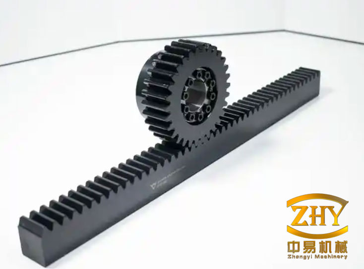
2. Platform lifting duty and load path
In a jack-up platform, the lifting system connects the hull or deck platform to the support legs. The rack and pinion gears are not merely a speed-reduction device; they are the final load-transfer pair between the platform and the seabed through the legs. Every static and dynamic load acting on the platform eventually passes through the pinion-rack mesh. These loads include the hull weight, variable deck load, wind load, wave and current load, inertial effects during transit and jacking, preload forces during leg penetration, and storm survival loads. Because the mesh is open or semi-open and operates at very low speed but very high torque, the design is controlled by strength and fatigue rather than by speed or power density alone.
| Operating state | Typical load character | Critical effect on rack and pinion gears |
|---|---|---|
| Leg preloading | High static force with short-term peaks | Tooth-root bending, rack tooth bearing, leg-rack weld stress |
| Jacking up or down | Cyclic force with slow motion and possible stick-slip | Tooth-flank wear, scuffing, contact fatigue, pinion root fatigue |
| Operating at elevation | Sustained static load plus wind and wave dynamics | Rack tooth root bending, pinion tooth root bending, brake and holding system load |
| Storm survival | Extreme dynamic load and load reversal | Tooth breakage, rack tooth plastic deformation, system strength limit |
| Transit or towing | Shock and vibration with legs partly raised | Impact damage, misalignment, uneven load sharing among pinions |
I treat the rack and pinion gears as a series chain of strength limits. The chain includes the motor, the reducer, the output shaft, the climbing pinion, the rack tooth, the rack body, and the welded connection to the leg. In most practical designs, the weakest controlled element should not be the rack, because the rack is long, welded, and expensive to replace. Instead, the climbing pinion is usually allowed to become the sacrificial or life-limited component. This philosophy influences every later comparison between rack and pinion gears and pin-wheel rack drives.
3. Conventional rack and pinion lifting arrangement
The conventional lifting unit usually contains an electric motor, a multi-stage gear reducer, a planetary reduction stage, and an output pinion. The motor supplies high-speed, low-torque input. The reducer converts this into low-speed, high-torque output. The output pinion, often called the climbing gear, meshes with the leg rack. The reducer may include several parallel shaft stages and one or two planetary stages. The output shaft carries the pinion and is supported by heavy bearings inside the lifting unit.
The basic transmission relations I use are:
$$i = \frac{n_{in}}{n_{out}} = \frac{z_2 z_4 z_6 \cdots}{z_1 z_3 z_5 \cdots}$$
$$T_{out} = T_{in} i \eta$$
$$F_L = \frac{T_{out}}{r_p}$$
$$v = \omega_p r_p = \frac{2 \pi n_p r_p}{60}$$
Here \(i\) is the total reduction ratio, \(n_{in}\) and \(n_{out}\) are input and output speeds, \(z\) denotes tooth numbers, \(T_{in}\) and \(T_{out}\) are torques, \(\eta\) is efficiency, \(F_L\) is the tangential lifting force at the pitch circle, \(r_p\) is the pinion pitch radius, \(v\) is the linear lifting speed, and \(\omega_p\) is the pinion angular velocity. For offshore lifting, \(v\) is intentionally small, often only a few tenths of a meter per minute or less. The torque, however, is extremely high. This combination produces very large tangential forces on the rack and pinion gears.
| Symbol | Meaning | Design significance |
|---|---|---|
| \(i\) | Total gear ratio | Determines motor speed and output torque |
| \(T_{out}\) | Output torque | Sets the lifting force at the pinion |
| \(F_L\) | Tangential lifting force | Directly loads rack and pinion teeth |
| \(r_p\) | Pinion pitch radius | Larger radius reduces tooth force but increases size |
| \(m\) | Module | Controls tooth size and bending capacity |
| \(b\) | Face width | Controls load distribution and contact area |
| \(\sigma_F\) | Tooth-root bending stress | Primary strength limit for rack and pinion gears |
| \(\sigma_H\) | Tooth-flank contact stress | Controls pitting and surface fatigue |
4. Failure modes of rack and pinion gears in offshore service
The failure modes I observe in heavy, low-speed, open rack and pinion gears are tooth-flank wear, scuffing or adhesive wear, pitting or contact fatigue, and tooth breakage. In offshore lifting, the most dangerous are root fatigue and final tooth fracture. Surface wear and pitting are also serious because they change the tooth profile, increase dynamic load, and accelerate subsequent root cracking. Because the mesh is often poorly lubricated or only periodically lubricated, the sliding contact at the tooth tip and root can be severe. Contamination by salt, sand, and water makes the lubrication condition worse.
For bending strength, I use a form similar to the international gear standards:
$$\sigma_F = \frac{F_t}{b m} Y_F Y_S Y_\beta K_A K_V K_{F\beta} K_{F\alpha}$$
For contact strength, I use:
$$\sigma_H = Z_E Z_H Z_\epsilon Z_\beta \sqrt{\frac{F_t}{d_p b} \frac{u+1}{u} K_A K_V K_{H\beta} K_{H\alpha}}$$
Here \(F_t\) is the tangential tooth force, \(b\) is face width, \(m\) is module, \(d_p\) is pinion reference diameter, \(u\) is the gear ratio, \(Y\) factors account for form, stress concentration, helix angle, and load distribution, and \(Z\) factors account for material elasticity, contact geometry, contact ratio, and helix angle. \(K_A\), \(K_V\), \(K_{F\beta}\), \(K_{F\alpha}\), \(K_{H\beta}\), and \(K_{H\alpha}\) represent application, dynamic, face load, and transverse load factors. For offshore rack and pinion gears, these factors can be large because the system is stiff, the load is uneven, and the environment introduces shock and misalignment.
| Failure mode | Root cause | Offshore consequence | Govern ing limit |
|---|---|---|---|
| Tooth-flank wear | Sliding, contamination, poor lubrication | Loss of profile, increased dynamic load, noise | Wear rate and allowable backlash |
| Scuffing or adhesive wear | High local pressure and temperature at low speed | Rapid surface damage | Lubricant film and surface treatment |
| Pitting or contact fatigue | Repeated contact stress above endurance | Surface spalling and crack initiation | \(\sigma_H \le \sigma_{HP}\) |
| Tooth-root fatigue | Repeated bending stress at root fillet | Crack growth and tooth loss | \(\sigma_F \le \sigma_{FP}\) |
| Tooth fracture | Overload, impact, or fatigue crack | Loss of lifting ability, unsafe platform | Ultimate bending strength |
5. Measured stress behavior and design limits
I have reviewed representative stress data for a large offshore rack and pinion system. The pinion had a very large module, few teeth, and a wide face. The rack was long and welded to the leg. During operation, the maximum stress on the rack contact face was higher than the maximum stress on the pinion contact face, and the pinion root stress became very high at certain meshing positions. The following table summarizes the observed maximum stresses at three meshing positions.
| Meshing position | Pinion root max stress / MPa | Pinion face max stress / MPa | Rack root max stress / MPa | Rack face max stress / MPa |
|---|---|---|---|---|
| Position A | 618 | 824 | 611 | 1700 |
| Position B | 737 | 691 | 460 | 1440 |
| Position C | 895 | 653 | 336 | 1310 |
From my interpretation, the rack face is the most heavily loaded contact zone, while the pinion root is the most critical bending zone. The rack face stress is high because the rack tooth is in contact with a small, hard pinion and because the load is concentrated over a limited contact band. The pinion root stress is high because the pinion has few teeth and a large module, so each tooth acts like a short, deep cantilever under a very large tangential force.
For design purposes, I do not use the same limit for every component. I set the system strength limit by the maximum tooth-root bending stress of the most critical tooth. I set the practical design limit by the service life of the climbing pinion, because the pinion is easier and cheaper to replace than the long rack. The rack should remain below its allowable contact and bending limits with a suitable margin. The following inequalities summarize my design logic:
$$\sigma_{F,pinion} \le \sigma_{FP,pinion}$$
$$\sigma_{F,rack} \le \sigma_{FP,rack}$$
$$\sigma_{H,rack} \le \sigma_{HP,rack}$$
$$\sigma_{H,pinion} \le \sigma_{HP,pinion}$$
$$S_F = \frac{\sigma_{F,lim}}{\sigma_F} \ge S_{F,min}$$
$$S_H = \frac{\sigma_{H,lim}}{\sigma_H} \ge S_{H,min}$$
If the rack and pinion gears are made from different materials, I take the smaller allowable stress for the pair when I evaluate the contact condition. I also check the rack tooth root and the weld toe at the leg because the rack is not an isolated body. The rack tooth, rack base, and weld form a single load path.
| Component | Material example | Module / mm | Tooth number | Face width / mm | Yield limit / MPa | Ultimate limit / MPa |
|---|---|---|---|---|---|---|
| Climbing pinion | SAE 4340 | 97 | 7 | 200 | 745 | 940 |
| Leg rack | A514 type steel | 97 | 97 | 240 | 805 | 890 |
6. Limitations of conventional rack and pinion gears
My practical concern with conventional rack and pinion gears is not that they cannot work. They clearly do work. The problem is that their life-cycle cost and manufacturing difficulty become severe as the platform size and load capacity increase. Large offshore rack and pinion gears often use modules close to 100 mm. A pinion with seven teeth and a module of 97 mm is enormous, heavy, and difficult to machine. The tooling, hobbing, grinding, heat treatment, and inspection equipment must be very large. Only a limited number of suppliers can produce such parts. If the pinion is damaged, the lifting unit must be opened or removed, and the pinion must be replaced as a single large component. The rack is even worse: it is welded along the leg, and replacement is a major offshore or dry-dock operation.
I summarize the main limitations as follows:
| Limitation | Effect on project |
|---|---|
| Very large module and few teeth | Large blank size, high cutting forces, difficult heat treatment, high cost |
| Large and heavy pinion | Difficult handling, high inertia, expensive bearings and shafts |
| Open or semi-open mesh | Contamination, poor lubrication, wear, pitting |
| Rack welded to leg | High replacement cost and long downtime |
| Uneven load sharing | Some pinions overloaded, root fatigue accelerated |
| Limited supplier base | Long lead time and high spare-part cost |
| Tooth-root fatigue | Risk of sudden tooth loss and unsafe lifting |
Because of these limitations, I consider it necessary to explore other transmission principles. The pin-wheel rack drive is one of the most promising alternatives because it preserves the rack-and-pinion layout but replaces the involute pinion with a pin wheel and changes the rack tooth form. The result is a transmission that is more open, more tolerant of poor lubrication, easier to repair, and potentially cheaper to manufacture.
7. Pin-wheel rack drive principle
A pin-wheel rack drive is a special form of rack and pinion transmission. Instead of a solid gear tooth, the driving wheel carries a set of cylindrical pins or pin sleeves around its periphery. These pins engage the teeth of a rack. The driving wheel is usually the pin wheel, and the rack is fixed to the platform leg or moving member. When the pin wheel rotates, the pins push the rack teeth, and the rack moves linearly. The mechanism is robust, simple to manufacture, and relatively easy to maintain. It is suitable for low-speed, heavy-load, dusty, and poorly lubricated environments, which is exactly the character of offshore lifting.
The transmission relation remains similar to that of rack and pinion gears:
$$v = \omega_w R_w$$
$$F_1 = \frac{T_w}{R_w}$$
$$P = F_1 v$$
Here \(\omega_w\) is the angular velocity of the pin wheel, \(R_w\) is the effective pitch radius, \(T_w\) is the output torque, \(F_1\) is the tangential force, \(P\) is the transmitted power, and \(v\) is the linear speed. The pin wheel usually runs at a low circumferential speed, often between 0.05 m/s and 0.5 m/s. The transmission ratio can range from about 5 to 30. The efficiency can reach about 0.90 to 0.93 without lubrication and about 0.93 to 0.95 with lubrication. These values are lower than those of a well-lubricated enclosed gearbox, but they are acceptable for a heavy offshore jacking system where robustness and maintainability matter more than peak efficiency.
8. Pin tooth structure and pin sleeve concept
In an ordinary pin-wheel rack drive, each pin is a cylindrical body mounted between two side plates of the pin wheel. The pin acts as a simply supported beam rather than a cantilever. This is a major mechanical advantage. A simply supported pin under a central or distributed load has a lower bending moment than a cantilever of the same length. The pin is easy to machine because it is a cylinder. It can be made from high-strength steel, surface hardened, or fitted with a sleeve. If one pin is damaged, it can be replaced individually without replacing the whole wheel.
When the pin wheel is the driving member, the tip of the pin or the tooth enters the mesh first. The relative motion at the tip can be sliding, which lowers efficiency and increases wear. To reduce this effect, I prefer a pin sleeve structure. A sleeve is placed over the pin, and the sleeve can rotate relative to the pin. When the sleeve contacts the rack tooth, the contact becomes closer to rolling contact instead of pure sliding contact. This reduces wear and extends the life of both the pin wheel and the rack.
| Feature | Ordinary pin | Pin with sleeve |
|---|---|---|
| Contact motion | Mostly sliding | Partly rolling |
| Wear rate | Higher | Lower |
| Efficiency | Lower | Higher than ordinary pin |
| Maintenance | Replace pin | Replace pin or sleeve |
| Lubrication demand | High | Moderate |
| Manufacturing | Simple | Slightly more complex |
| Offshore suitability | Acceptable | Preferred in my assessment |
9. Geometry and strength design of pin-wheel rack drives
For a pin-wheel rack drive, I begin with the known transmission parameters: required tangential force, allowable contact stress, allowable bending stress, rack face width, pin diameter, and pitch. I then calculate the main geometry and verify the strength. The key parameters are the rack face width coefficient \(\phi\), the number of rack teeth, the pin diameter \(d_p\), and the pitch \(p\). The contact strength design formula I use is:
$$d_p \ge \frac{310}{\sigma_{HP}} \sqrt{\frac{F_1}{\phi}}$$
The corresponding contact strength check is:
$$\sigma_H = \frac{310}{d_p} \sqrt{\frac{F_1}{\phi}} \le \sigma_{HP}$$
Here \(d_p\) is the pin diameter in mm, \(F_1\) is the rated tangential force in N, \(\sigma_{HP}\) is the allowable contact stress in MPa, \(\phi\) is the rack face width coefficient, and \(\sigma_H\) is the calculated contact stress in MPa. If the pin wheel and the rack are made from different materials, I use the smaller allowable contact stress for the pair.
For pin bending strength, I use:
$$\sigma_{F2} = \frac{2.5 F_1 (L – b)}{d_p^3} \le \sigma_{F2p}$$
Here \(\sigma_{F2}\) is the calculated bending stress in the pin, \(L\) is the effective pin length in mm, \(b\) is the rack face width in mm, and \(\sigma_{F2p}\) is the allowable bending stress of the pin material in MPa. Because the pin is supported at both ends, the bending moment is lower than that of a cantilever, and the failure mode is easier to predict.
For the pin wheel side plate, I check the bearing or crushing stress:
$$\sigma_{pr} = \frac{F_1}{2 d_p \delta} \le \sigma_{prp}$$
Here \(\sigma_{pr}\) is the calculated crushing stress in MPa, \(\delta\) is the side plate thickness in mm, and \(\sigma_{prp}\) is the allowable crushing stress. For a common structural steel such as Q235, the allowable crushing stress may be taken as about 98 MPa to 118 MPa. For offshore high-strength steel, the allowable value should be selected according to the material specification and safety factor.
| Parameter | Symbol | Design role | Typical check |
|---|---|---|---|
| Pin diameter | \(d_p\) | Controls contact area and pin bending stiffness | \(d_p \ge \frac{310}{\sigma_{HP}} \sqrt{\frac{F_1}{\phi}}\) |
| Tangential force | \(F_1\) | Primary load on pin and rack | \(F_1 = T_w / R_w\) |
| Rack face width coefficient | \(\phi\) | Relates face width to pitch or diameter | Selected from layout and wear allowance |
| Pin effective length | \(L\) | Affects bending moment | \(L > b\) for support and clearance |
| Rack face width | \(b\) | Controls contact length | \(b \le L\) |
| Side plate thickness | \(\delta\) | Controls pin support bearing stress | \(\sigma_{pr} \le \sigma_{prp}\) |
| Contact stress | \(\sigma_H\) | Surface fatigue limit | \(\sigma_H \le \sigma_{HP}\) |
| Pin bending stress | \(\sigma_{F2}\) | Pin fracture limit | \(\sigma_{F2} \le \sigma_{F2p}\) |
At the pitch point, I evaluate the local contact geometry. In many pin-wheel rack calculations, the equivalent curvature radii at the contact point are approximated as a multiple of the pin diameter. I use the following geometric relations as a first estimate:
$$\rho_{pin} = 1.5 d_p$$
$$\rho_{rack} = 0.5 d_p$$
These values help me estimate the contact stress and the pressure angle variation. The exact values depend on the rack tooth profile, the pin diameter, the pitch, and the center distance. I therefore treat the above relations as a starting point and refine them with a detailed contact model when the design is mature.
10. Comparison of rack and pinion gears with pin-wheel rack drives
I compare the two systems on the basis of structure, efficiency, volume, weight, force condition, lubrication, repair cost, and manufacturing cost. The comparison is not one-sided. Conventional rack and pinion gears have higher efficiency and a smaller package for a given torque. Pin-wheel rack drives are larger and heavier, and their efficiency is lower. However, the pin-wheel rack drive is easier to manufacture, easier to repair, and more tolerant of a poor lubrication environment. In offshore lifting, these advantages can outweigh the disadvantages.
| Comparison item | Conventional rack and pinion gears | Pin-wheel rack drive |
|---|---|---|
| Structure | Simple and compact | Slightly more complex but open |
| Transmission efficiency | High | Lower |
| Volume for same torque | Smaller | Larger |
| Weight | Lighter | Heavier |
| Pinion or wheel tooth force condition | Cantilever-like tooth bending | Simply supported pin bending |
| Lubrication | More demanding | More tolerant |
| Repair cost | High | Low |
| Manufacturing cost | High | Lower |
| Replacement strategy | Replace large pinion | Replace individual pin or sleeve |
| Offshore environmental tolerance | Moderate | Good |
| Design maturity for jack-up platforms | High | Emerging |
My assessment is that the pin-wheel rack drive is not a drop-in replacement for all rack and pinion gears. It is a complementary technology. For new platforms with moderate lifting force and a strong need to reduce maintenance cost, it may be attractive. For very large platforms with extreme storm loads, the larger size and lower efficiency of the pin-wheel rack drive must be evaluated carefully. In both cases, the design should be based on the same principles: define the load cases, calculate the tooth or pin forces, check bending and contact strength, and verify the fatigue life.
11. Rack tooth profile selection for pin-wheel drives
The rack tooth profile has a strong influence on motion stability. In a pin-wheel rack drive, the pin wheel center velocity should be as constant as possible. If the center velocity fluctuates, the platform may experience vibration, shock, and uneven load. The rack profile determines how the contact point moves and how the pressure angle changes during mesh. I have considered straight profiles, convex circular-arc profiles, concave circular-arc profiles, and cycloidal profiles.
For a straight tooth profile, the rack tooth is a straight line. When two adjacent pins alternate in mesh, the pin wheel center velocity has a sudden decrease at the transition. This produces a small but sharp velocity fluctuation. For a convex circular-arc profile, the pressure angle changes during mesh, and the velocity fluctuation is reduced compared with the straight profile. If the number of pins is increased, the next pin can enter the mesh before the previous pin leaves, which further smooths the motion. For a concave circular-arc profile, the center velocity is always fluctuating, but the amplitude is smaller than that of the straight or convex profiles. This is favorable when the number of pins cannot be increased or when the size and weight of the drive must be reduced. For a cycloidal profile, the mesh has a single-tooth contact zone and a double-tooth contact zone. In the double-tooth zone, the load tends to be shared, but at the transition between the single and double zones there is a load step. This can cause vibration and uneven wear.
| Rack profile | Velocity behavior | Load behavior | Preferred use |
|---|---|---|---|
| Straight | Sudden velocity decrease at pin transition | Simple but impact-prone | Low-cost, low-speed, less critical motion |
| Convex circular arc | Smaller velocity fluctuation than straight | Pressure angle changes gradually | General pin-wheel drives with moderate pin count |
| Concave circular arc | Smallest fluctuation among circular arcs | More uniform than convex | When pin number is limited or size must be reduced |
| Cycloidal | Single and double mesh zones | Load step at zone transition | Special designs with detailed dynamic analysis |
In my view, the concave circular-arc profile is often the best compromise for offshore pin-wheel rack drives. It offers smoother motion than the straight or convex profile and is easier to manufacture than a precise cycloidal profile. However, I would not select it without a full kinematic and contact analysis, because the actual pressure angle, contact ratio, and load distribution depend on the pin diameter, pitch, rack tooth height, and center distance.
12. Strength and fatigue verification for offshore duty
For offshore duty, I do not accept a static strength check alone. I require a fatigue check for the pinion or pin wheel, the rack tooth, the pin, and the rack weld. The load spectrum must include normal jacking, preloading, storm loading, and transit shock. I use a simple cumulative damage rule:
$$D = \sum_{i=1}^{n} \frac{n_i}{N_i}$$
$$D \le D_{allow}$$
Here \(n_i\) is the number of cycles at stress level \(i\), \(N_i\) is the allowable number of cycles at that stress level, and \(D_{allow}\) is the allowable cumulative damage. For rack and pinion gears, the stress-life curve is often expressed in terms of contact stress and bending stress. For pin-wheel rack drives, the pin bending stress and the contact stress between the pin and rack are the critical quantities.
I also check the safety factors for yield and ultimate strength:
$$S_y = \frac{\sigma_y}{\sigma_{max}}$$
$$S_u = \frac{\sigma_u}{\sigma_{max}}$$
Here \(\sigma_y\) is the yield strength, \(\sigma_u\) is the ultimate strength, and \(\sigma_{max}\) is the maximum calculated stress. For offshore lifting, the minimum safety factors should be selected according to the classification rules and the consequences of failure. Because the lifting system supports the entire platform, I prefer a conservative approach, especially for the rack and pinion gears.
| Check | Equation | Purpose |
|---|---|---|
| Bending safety | \(S_F = \sigma_{F,lim} / \sigma_F\) | Prevent tooth-root or pin fatigue |
| Contact safety | \(S_H = \sigma_{H,lim} / \sigma_H\) | Prevent pitting and surface fatigue |
| Yield safety | \(S_y = \sigma_y / \sigma_{max}\) | Prevent local yielding |
| Ultimate safety | \(S_u = \sigma_u / \sigma_{max}\) | Prevent fracture under extreme load |
| Cumulative damage | \(D = \sum n_i / N_i\) | Estimate fatigue life under variable load |
| Bearing crushing | \(\sigma_{pr} = F_1 / (2 d_p \delta)\) | Protect pin support plates |
13. Feasibility matrix for offshore lifting
I built a simple weighted matrix to compare the two transmission concepts for a jack-up lifting system. The scores are qualitative, but they show how the decision depends on project priorities. If the priority is minimum size and maximum efficiency, conventional rack and pinion gears win. If the priority is low maintenance cost, easy repair, and tolerance to a harsh environment, the pin-wheel rack drive is strong.
| Criterion | Weight | Rack and pinion gears score | Pin-wheel rack drive score | Weighted advantage |
|---|---|---|---|---|
| Load capacity | 0.18 | 9 | 8 | Rack and pinion gears |
| Compactness | 0.12 | 9 | 6 | Rack and pinion gears |
| Efficiency | 0.10 | 9 | 7 | Rack and pinion gears |
| Manufacturing cost | 0.15 | 5 | 8 | Pin-wheel rack drive |
| Maintenance cost | 0.15 | 5 | 9 | Pin-wheel rack drive |
| Environmental tolerance | 0.12 | 6 | 9 | Pin-wheel rack drive |
| Fatigue reliability | 0.10 | 7 | 7 | Neutral |
| Design maturity | 0.08 | 10 | 4 | Rack and pinion gears |
From my weighted view, the conventional rack and pinion gears remain the default for high-load, high-consequence platforms because of their maturity and compactness. The pin-wheel rack drive is attractive for projects where maintenance access is difficult, where replacement of a large pinion is prohibitively expensive, or where the operator wants to reduce the risk of a long rack replacement. It is also attractive as a hybrid concept: use conventional rack and pinion gears where the load is highest, and use pin-wheel rack drives in auxiliary or lower-load positions.
14. Design recommendations I would apply
I would follow these steps when comparing or designing either system:
1. Define the full load spectrum, including preload, jacking, operating, storm, and transit cases. Do not use a single static load for the rack and pinion gears.
2. Calculate the tangential force at the pitch circle using the output torque and the effective radius. For rack and pinion gears, this force directly enters the bending and contact equations.
3. Check the tooth-root bending stress first, because root fatigue is the most dangerous failure mode. Then check the contact stress to control pitting and wear.
4. For pin-wheel rack drives, check the pin bending stress, the pin-rack contact stress, and the side plate crushing stress. Use a pin sleeve if sliding wear is a concern.
5. Select the rack tooth profile according to the required motion stability. Use a concave circular-arc profile when smooth motion is important and the pin count is limited. Use a convex or straight profile only after confirming that the velocity fluctuation is acceptable.
6. Use a conservative safety factor for the rack because it is welded and difficult to replace. In many cases, I would make the climbing pinion or the pin wheel the life-limited component.
7. Verify the rack weld and the leg structure. The best rack and pinion gears will still fail if the weld toe cracks or the leg wall yields.
8. Include lubrication, sealing, inspection, and replacement access in the design from the beginning. A transmission that cannot be maintained offshore will not be reliable, no matter how strong it is.
15. Concluding view
I conclude that conventional rack and pinion gears remain a powerful and proven solution for jack-up offshore platform lifting. Their high efficiency, compact size, and mature design rules make them difficult to replace in the most demanding applications. However, their limitations are real: very large modules, few teeth, high manufacturing cost, difficult repair, and severe tooth-root and contact loading. The pin-wheel rack drive offers a credible alternative for certain offshore duties. It uses simple cylindrical pins or pin sleeves, transfers load through a simply supported pin, tolerates poor lubrication, and allows individual pins to be replaced without replacing the whole wheel. Its lower efficiency, larger size, and heavier weight must be accepted in exchange for lower life-cycle cost and easier maintenance.
My recommendation is therefore not to abandon rack and pinion gears, but to develop the pin-wheel rack drive as a parallel technology. The next steps should include detailed dynamic modeling of the pin-rack contact, fatigue testing of pin sleeves under salt-water contamination, optimization of the rack tooth profile for constant center velocity, and full-scale validation of the load-sharing behavior among multiple pin wheels. If those steps are successful, the pin-wheel rack drive can provide a valuable new option for the next generation of offshore lifting systems, while conventional rack and pinion gears continue to serve as the benchmark for strength, stiffness, and reliability.