
I evaluate the manufacturing route for forged gear blanks used in rear-axle driven spiral bevel gears by comparing three industrial options: hot die forging on a large mechanical press, forging on a steam-air or counterblow hammer, and expanding-rolling after open-die preforming. My focus is not only on the nominal forging operation but on the complete technical-economic system that determines whether forged gear blanks can be produced competitively at large volume. That system includes billet preparation, heating, preforming, piercing, expanding-rolling, sizing, die cost and life, equipment mass and foundation depth, building height and crane capacity, labor, fuel and power consumption, maintenance, scrap recovery, and final piece cost. In my assessment, the expanding-rolling route is the most attractive solution for a large family of annular forged gear blanks, especially when the annual demand is high, the geometry is rotationally symmetric, and the plant does not wish to install a very large press line or a heavy hammer line.
The conventional assumption is that a large mechanical press gives the best forged gear blanks because it combines high productivity with tight tolerances. That statement is true only when the capital cost of the press line, the trim press, the heating system, the foundations, the building, and the tooling are all justified by the product mix. A heavy hammer route is often treated as a flexible fallback, but it consumes more material and energy and creates a more difficult working environment. The expanding-rolling route changes the manufacturing logic: instead of forcing the entire gear-blank volume into a closed die with flash and a thick piercing web, I form a preform with a controlled blind bore, pierce a small central slug, and then expand the ring-shaped preform between a rotating roll and a mandrel until the required outside diameter, bore profile, and axial height are reached. The result is a family of forged gear blanks with little or no flash, a small punched slug, favorable grain flow, and significantly lower equipment mass.
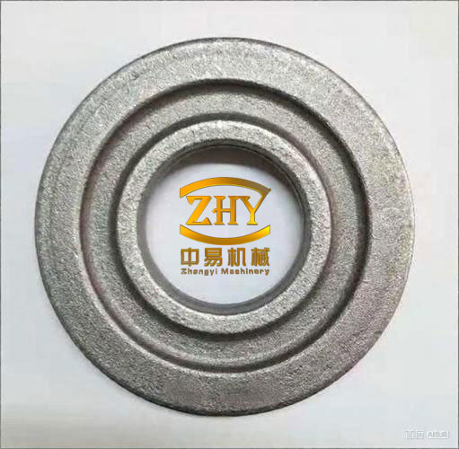
Process routes I compare. In the press-forging route, I heat the billet, upset it, remove scale, perform a preforge step, finish forge in a large mechanical press, and then trim the flash and pierce the central web in a separate press. This route is productive and gives small machining allowances, but the flash and the piercing web are unavoidable material losses. In the hammer route, I heat the billet, upset and perform preliminary shaping, finish forge under a steam-air hammer or a counterblow hammer, and trim and pierce afterward. The hammer route is flexible but requires larger draft angles and fillet radii, generates more flash and web, and demands steam, compressed air, boiler plant, and a robust building with vibration isolation. In the expanding-rolling route, I saw the billet, heat it, upset it, punch a stepped blind hole, punch the central slug, expand-roll the ring preform, and size the final forged gear blanks in a friction press or another short-stroke press. The stepped blind hole is important because it provides locating geometry for the slug punch and helps control the axial metal distribution before expanding. The punch depth and punch front step must be controlled within a narrow band so that the subsequent expanding-rolling operation has a stable preform volume and a centered bore.
| Process step | Large mechanical press route | Hammer route | Expanding-rolling route |
|---|---|---|---|
| Billet preparation | Saw or shear; weight control important | Saw or shear; weight control important | Saw; weight control important |
| Heating | Induction or continuous furnace | Flame furnace, gas or oil | Induction or controlled flame furnace |
| Preforming | Upset, descale, preforge | Upset and preliminary hammer shaping | Upset, blind-hole punch, slug punch |
| Main forming | Closed-die finish forging | Open or closed-die hammer forging | Expanding-rolling between roll and mandrel |
| Trimming and piercing | Trim press and pierce press | Trim press and pierce press | Small slug punched before rolling; little or no flash |
| Sizing | Usually integrated by die accuracy | Often requires correction | Friction-press or short-stroke press sizing |
| Typical material condition | Flash and web losses | Largest flash and web losses | Lowest flash and web losses |
| Typical equipment character | Very heavy press line | Heavy hammer line with auxiliary plant | Moderate presses plus expanding machine |
Material utilization is the first discriminator. For any forged gear blanks, I define the blank material utilization as the ratio of finished forged mass to billet mass, and the component material utilization as the ratio of finished part mass to billet mass. The two definitions must not be mixed, because a process can produce an excellent near-net forged blank while still having a low component utilization if the machining allowance is large. I use the following definitions:
$$
\eta_{\mathrm{blank}}=\frac{m_{\mathrm{forged}}}{m_{\mathrm{billet}}}\times 100\%
$$
$$
\eta_{\mathrm{part}}=\frac{m_{\mathrm{part}}}{m_{\mathrm{billet}}}\times 100\%
$$
$$
m_{\mathrm{billet}}=m_{\mathrm{forged}}+m_{\mathrm{flash}}+m_{\mathrm{web}}+m_{\mathrm{scale}}+m_{\mathrm{scrap}}
$$
Here, the flash and web terms are the dominant differences among the three routes. In the press route, the flash and web are smaller than in the hammer route but still present. In the hammer route, the flash, web, draft, and fillet allowances are larger. In the expanding-rolling route, the preform is designed as an annular body, so the central material is removed as a small slug rather than as a thick web, and the outer periphery is formed by rolling rather than by escape into a flash land. For a given finished forged gear blank, this usually gives the highest blank utilization and the lowest billet mass.
| Material-balance item | Large mechanical press | Hammer | Expanding-rolling |
|---|---|---|---|
| Flash loss | Medium | High | Very low |
| Piercing-web loss | Medium | High | Low, because a small slug is punched before rolling |
| Draft and fillet allowance | Low to medium | High | Low after sizing |
| Machining allowance | Low | Medium to high | Low to medium |
| Scale loss | Controlled | Often higher | Controlled by induction heating |
| Relative blank material utilization | High | Medium | Highest |
| Relative component material utilization | Medium to high | Low to medium | Highest |
| Relative billet mass for same forged gear blank | Medium | High | Lowest |
I express the annual material saving of one route over another as a simple mass balance. If the annual output is N forged gear blanks, the billet mass of the reference route is mb,ref, and the billet mass of the improved route is mb,new, then the annual saving is:
$$
\Delta S=N\left(m_{b,\mathrm{ref}}-m_{b,\mathrm{new}}\right)
$$
$$
V_{\mathrm{saving}}=\Delta S\cdot p_{\mathrm{steel}}
$$
where psteel is the effective steel price including handling and scrap credit. For example, if N is one hundred thousand pieces per year and the expanding-rolling route saves 1.5 kg of billet per forged gear blank, the annual steel saving is 150 t. At an effective value of 4,000 to 6,000 currency units per tonne, the annual saving is 0.6 to 0.9 million currency units before considering energy and tooling. The actual number depends on the gear size, but the direction is robust: the expanding-rolling route reduces the billet mass because the process does not need a thick flash land or a large central web.
| Parameter | Large mechanical press | Hammer | Expanding-rolling |
|---|---|---|---|
| Finished part mass | 100 | 100 | 100 |
| Forged blank mass, index | 132 | 142 | 118 |
| Billet mass, index | 146 | 164 | 126 |
| Blank utilization, index | 100 | 93 | 112 |
| Component utilization, index | 100 | 89 | 116 |
| Relative scrap mass, index | 100 | 128 | 72 |
Forging quality and dimensional control. I do not accept material saving if it reduces the quality of forged gear blanks below the requirement of the subsequent gear-cutting and heat-treatment operations. The press route gives excellent repeatability when the press, die, heater, and billet weight are well controlled. The hammer route gives adequate structural quality but poorer dimensional repeatability, larger draft angles, and more machining stock. The expanding-rolling route gives a favorable continuous grain flow around the bore and rim, because the ring is progressively expanded rather than simply squeezed in a closed cavity. The expanding process also closes internal porosity and aligns the flow lines along the circumferential direction, which is beneficial for the tooth root and rim of a spiral bevel gear. The limiting factors are temperature loss, preform centering, mandrel wear, roll speed, and the stability of the blind-hole depth. A final sizing operation in a friction press improves flatness, height tolerance, bore roundness, and the outside-diameter tolerance of the forged gear blanks.
| Quality characteristic | Large mechanical press | Hammer | Expanding-rolling plus sizing |
|---|---|---|---|
| Dimensional repeatability | Excellent | Fair | Good to excellent after sizing |
| Draft requirement | Low | High | Very low or none on rolled surfaces |
| Machining allowance | Low | Medium to high | Low to medium |
| Flash | Present | Large | Very small or absent |
| Grain flow around bore | Good | Good | Excellent due to circumferential expansion |
| Bore centering | Good | Fair | Good if blind hole and mandrel are controlled |
| Flatness after forming | Good | Fair | Improved by final sizing |
| Sensitivity to billet weight variation | Medium | High | Medium, reduced by volume-controlled preform |
| Sensitivity to temperature variation | Medium | High | Medium to high; induction heating is preferred |
| Surface defects from flash folding | Low | Medium | Low |
Equipment mass, foundation, building height, and area. The most visible advantage of expanding-rolling for forged gear blanks is that it avoids the need for a very large die-forging press or a very heavy hammer. A large mechanical press line for a rear-axle driven bevel gear blank requires a press with a very high nominal force, a heavy crown and bed, a large flywheel or clutch system, a deep foundation, and a tall building for assembly and maintenance. A hammer line requires a massive anvil block, vibration isolation, a boiler or compressed-air plant, and a tall crane bay. In contrast, the expanding-rolling route uses an upsetting press, a punching press, an expanding-rolling machine, and a sizing press. Each unit is smaller, and the total installed mass is lower, even though the number of machines is larger.
$$
H_{\mathrm{building}}=h_{\mathrm{machine}}+h_{\mathrm{lifting}}+h_{\mathrm{rigging}}+h_{\mathrm{safety}}
$$
$$
D_{\mathrm{foundation}}=f\left(W_{\mathrm{machine}},F_{\mathrm{impact}},S_{\mathrm{soil}}\right)
$$
In my comparison, the building height for the expanding-rolling line is governed by the tallest individual machine and the crane hook height, not by the need to remove a press tie rod or to lift a hammer ram. The foundation depth is governed by the expanding machine and the presses, not by a massive hammer anvil. The floor area is larger than a single press cell but smaller than a complete press line with its coil feed, trim press, and transfer equipment. The crane capacity is also lower because the heaviest lift is a roll assembly, a mandrel, or a press ram, not a press crown or a hammer anvil. This reduces the civil-construction cost per square meter and the structural steel cost per tonne of installed equipment.
| Infrastructure item | Large mechanical press | Hammer | Expanding-rolling |
|---|---|---|---|
| Maximum equipment height | Very high | High | Moderate |
| Required building height | Highest | High | Lowest |
| Crane capacity | High | High | Moderate |
| Foundation depth | Deep | Deepest due to anvil and isolation | Moderate |
| Foundation mass per machine | Very high | Very high | Moderate |
| Vibration isolation requirement | Medium | Very high | Low to medium |
| Boiler or gas plant requirement | Low if induction heated | High if steam driven | Low if induction heated |
| Relative building volume | 100 | 110 | 78 |
| Relative foundation cost | 100 | 125 | 70 |
| Relative crane and structural cost | 100 | 108 | 82 |
Capital investment. I calculate the total investment for a forged gear blanks line as the sum of process equipment, handling equipment, tooling, civil works, foundations, and related utilities. The formula I use is:
$$
I_{\mathrm{total}}=I_{\mathrm{process}}+I_{\mathrm{handling}}+I_{\mathrm{tooling}}+I_{\mathrm{civil}}+I_{\mathrm{foundation}}+I_{\mathrm{utility}}+I_{\mathrm{contingency}}
$$
$$
I_{\mathrm{annualized}}=I_{\mathrm{total}}\frac{i(1+i)^n}{(1+i)^n-1}
$$
where i is the discount rate and n is the depreciation period. The expanding-rolling line may contain more individual machines, but the sum of their prices is lower than the price of one very large press line or one heavy hammer line. The auxiliary investment is also lower: no large boiler house, no massive steam distribution system, no very large compressed-air station for a steam hammer, and no special high-bay crane. The related investment for power distribution and cooling water is moderate because induction heating and hydraulic units require controlled power and water, but this is still less than the civil and utility burden of a heavy hammer line.
| Investment category | Large mechanical press | Hammer | Expanding-rolling |
|---|---|---|---|
| Main process equipment | 100 | 82 | 58 |
| Heating equipment | 85 | 70 | 76 |
| Trim and pierce equipment | 45 | 40 | 20 |
| Handling and transfer | 50 | 35 | 45 |
| Tooling and dies | 70 | 55 | 35 |
| Foundations and civil works | 100 | 125 | 62 |
| Building and crane | 100 | 112 | 76 |
| Utility and related plant | 55 | 95 | 48 |
| Total relative investment | 100 | 96 | 66 |
The numerical indices in Table 6 should be read as a planning comparison, not as a universal quotation. The conclusion I draw is stable: for the same family of forged gear blanks, the expanding-rolling route has the lowest total capital requirement because it replaces a single very large machine with several moderate machines and avoids the most expensive civil-construction and auxiliary-plant items. This matters because many gear manufacturers can justify a moderate press and an expanding machine but cannot justify a single large die-forging press whose cost and infrastructure dominate the entire project.
Dies, rolls, mandrels, and tool life. Tooling is a major cost driver for forged gear blanks. In the press route, the finish die is large, heavily loaded, and expensive. The die must withstand high contact pressure, thermal cycling, and wear at the flash land. In the hammer route, the die is subjected to impact loading, and the die life is often limited by impact fatigue and heat checking. In the expanding-rolling route, the tooling consists of a preform punch, a slug punch, an expanding roll, a mandrel, and a sizing die. These tools are smaller and simpler, and the rolling action is more gradual than a single high-impact blow. The roll and mandrel wear is concentrated on a small contact zone, so the tools can be replaced or refinished at lower cost. The sizing die is also simpler than a full closed die because the expanding operation has already produced the main geometry.
$$
C_{\mathrm{tool,piece}}=\frac{C_{\mathrm{tool}}+N_{\mathrm{refurb}}C_{\mathrm{refurb}}}{L_{\mathrm{tool}}N_{\mathrm{cavity}}\eta_{\mathrm{availability}}}
$$
$$
W_{\mathrm{die}}=\rho V_{\mathrm{die}}
$$
Here, Ltool is the tool life in strokes or pieces, Ncavity is the number of cavities, and Nrefurb is the number of allowable refurbishments. Because the expanding-rolling tools are smaller and less complex, the tooling inventory for a given annual output of forged gear blanks is lower. The die steel consumption per tonne of forging is also lower. This is not a secondary issue: in high-volume gear-blank production, the tooling cost per piece can determine whether a process is profitable.
| Tooling characteristic | Large mechanical press | Hammer | Expanding-rolling |
|---|---|---|---|
| Relative die or tool mass | 100 | 85 | 45 |
| Relative tooling cost | 100 | 78 | 48 |
| Relative number of refurbishments | 3 to 5 | 2 to 4 | 4 to 8 for rolls and mandrels |
| Relative tool life per cost unit | 100 | 82 | 135 |
| Relative die steel consumption per tonne | 100 | 112 | 68 |
| Relative tooling cost per piece | 100 | 95 | 62 |
| Tool handling requirement | Heavy crane | Heavy crane | Moderate crane or manipulator |
Productivity, personnel, and labor content. The press route has the highest productivity per stroke, but the complete line includes heating, transfer, trimming, piercing, and inspection. The hammer route has a high stroke rate but requires skilled hammer operators and more correction work. The expanding-rolling route is cyclic: upset, punch, pierce, roll, and size. The expanding step itself is not instantaneous, but it is short. The handling time between operations can dominate if the line is not mechanized. Therefore, I evaluate productivity using the complete cycle, not the main forming operation alone:
$$
Q_{\mathrm{hour}}=\frac{3600}{t_{\mathrm{forming}}+t_{\mathrm{handling}}+t_{\mathrm{heating\ buffer}}+t_{\mathrm{inspection}}}
$$
$$
Q_{\mathrm{year}}=Q_{\mathrm{hour}}H_{\mathrm{shift}}N_{\mathrm{shift}}\eta_{\mathrm{availability}}\eta_{\mathrm{quality}}
$$
In a manually operated expanding-rolling cell, the cycle time for medium-sized forged gear blanks can be comparable to a hammer line but lower than a large press line. If I add mechanized transfer, a walking beam or robot between the press and the expanding machine, and a second heating position, the output can exceed the hammer line and approach the press line for this product family. The number of operators is slightly higher than a hammer cell because there are more machines, but the physical effort and skill demand are lower. The labor content per piece is therefore competitive, and the working environment is significantly better: lower noise, lower vibration, and less exposure to flame and scale.
| Parameter | Large mechanical press | Hammer | Expanding-rolling |
|---|---|---|---|
| Relative main forming rate | 100 | 70 | 75 |
| Relative complete-line productivity, manual | 100 | 78 | 80 |
| Relative complete-line productivity, mechanized | 100 | 80 | 92 |
| Operators per cell | 3 to 4 | 3 to 4 | 4 to 5 |
| Relative labor content per piece | 100 | 115 | 98 |
| Physical effort | Medium | High | Medium to low |
| Noise and vibration | Medium | High | Low to medium |
| Skill sensitivity | Medium | High | Medium |
| Automation compatibility | High | Medium | High |
Energy and utility consumption. I separate the thermal energy needed to heat the billet from the mechanical energy needed to deform it and the auxiliary energy needed for hydraulics, cooling, compressed air, and handling. The minimum theoretical heating energy is:
$$
Q_{\mathrm{heat}}=m_{\mathrm{billet}}c_p\left(T_{\mathrm{forge}}-T_{\mathrm{ambient}}\right)
$$
$$
E_{\mathrm{heat}}=\frac{Q_{\mathrm{heat}}}{\eta_{\mathrm{furnace}}}
$$
For forged gear blanks, the actual heating energy is always higher than the theoretical value because of scale, radiation, opening losses, and conveyor losses. Induction heating gives better surface control and lower scale loss, but it has a high electrical demand. A flame furnace has a lower electrical demand but a higher total fuel consumption and a larger scale loss. The hammer route is penalized because a steam-air hammer needs steam or compressed air, and the boiler or compressor plant has additional losses. The press route is efficient in mechanical terms but still requires a large installed power for the press, the trim press, and the handling system. The expanding-rolling route has moderate press power, moderate induction power, and lower auxiliary plant demand. The absence of a massive hammer anvil also reduces the energy associated with vibration and foundation losses.
| Energy or utility item | Large mechanical press | Hammer | Expanding-rolling |
|---|---|---|---|
| Billet heating energy | 100 | 108 | 98 |
| Main forming energy | 100 | 125 | 72 |
| Trim and pierce energy | 45 | 42 | 18 |
| Hydraulic and cooling power | 35 | 20 | 48 |
| Compressed air or steam | 25 | 110 | 22 |
| Relative total energy per piece | 100 | 128 | 84 |
| Relative peak electrical demand | 100 | 82 | 78 |
| Relative scale loss | 100 | 120 | 78 |
| Relative CO2 intensity from energy | 100 | 124 | 86 |
Unit-cost model. The final decision for forged gear blanks must be based on unit cost, not on any single index. I use a cost model that includes material, direct labor, equipment depreciation, tooling, energy, maintenance, overhead, quality cost, and scrap credit:
$$
C_{\mathrm{unit}}=C_{\mathrm{material}}+C_{\mathrm{labor}}+C_{\mathrm{depreciation}}+C_{\mathrm{tool}}+C_{\mathrm{energy}}+C_{\mathrm{maintenance}}+C_{\mathrm{overhead}}+C_{\mathrm{quality}}-R_{\mathrm{scrap}}
$$
$$
C_{\mathrm{material}}=m_{\mathrm{billet}}p_{\mathrm{steel}}-\left(m_{\mathrm{flash}}+m_{\mathrm{web}}+m_{\mathrm{scale}}\right)p_{\mathrm{scrap}}
$$
$$
C_{\mathrm{depreciation}}=\frac{I_{\mathrm{annualized}}}{Q_{\mathrm{year}}}
$$
$$
C_{\mathrm{energy}}=\frac{E_{\mathrm{unit}}p_{\mathrm{energy}}}{m_{\mathrm{forged}}}
$$
When I apply this model to the three routes, the press route wins on labor and dimensional quality but loses on capital and material. The hammer route loses on material, energy, tooling, and labor environment. The expanding-rolling route wins on material, capital, tooling, and energy, while remaining competitive on labor and quality. The final unit cost therefore favors expanding-rolling for large-volume production of annular forged gear blanks. The press route remains attractive when the product mix is very broad, when the geometry is difficult to roll, or when the plant already has a large press and can fill its capacity. The hammer route remains useful for low-volume or repair production, but it is not my preferred solution for a dedicated high-volume gear-blank line.
| Cost element | Large mechanical press | Hammer | Expanding-rolling |
|---|---|---|---|
| Material and scrap credit | 100 | 112 | 86 |
| Direct labor | 100 | 115 | 98 |
| Equipment depreciation | 100 | 94 | 72 |
| Tooling | 100 | 95 | 62 |
| Energy | 100 | 128 | 84 |
| Maintenance | 100 | 110 | 82 |
| Overhead and building | 100 | 112 | 78 |
| Quality and rework | 100 | 115 | 92 |
| Total relative unit cost | 100 | 107 | 84 |
Weighted technical-economic score. Because the decision involves several criteria that do not share the same units, I use a weighted score as a cross-check. I assign weights according to the priorities of a high-volume gear-blank plant: material utilization, quality, capital, tooling, energy, labor, and environmental conditions. The score is:
$$
S=\sum_{i=1}^{n}w_i s_i
$$
$$
\sum_{i=1}^{n}w_i=1
$$
I score each criterion from 1 to 5, where 5 is best. The result is not a substitute for a detailed quotation, but it prevents a single attractive criterion from dominating the decision. In my scoring, expanding-rolling leads on material, capital, tooling, energy, and environment; the press leads on dimensional repeatability and very high-volume productivity; the hammer leads only on low initial complexity and flexibility for small batches.
| Criterion | Weight | Press score | Hammer score | Expanding-rolling score |
|---|---|---|---|---|
| Material utilization | 0.20 | 4 | 3 | 5 |
| Dimensional quality | 0.15 | 5 | 3 | 4 |
| Capital investment | 0.15 | 2 | 3 | 5 |
| Tooling cost and life | 0.10 | 3 | 3 | 5 |
| Energy consumption | 0.10 | 4 | 2 | 5 |
| Labor and environment | 0.10 | 4 | 2 | 5 |
| Productivity | 0.10 | 5 | 3 | 4 |
| Process flexibility | 0.05 | 4 | 5 | 3 |
| Maintenance simplicity | 0.05 | 3 | 3 | 4 |
| Weighted total | 1.00 | 3.70 | 3.05 | 4.55 |
Where expanding-rolling is the best choice. I recommend expanding-rolling for forged gear blanks when the following conditions are satisfied: the blank is annular or approximately annular; the outside diameter is within the capacity of the expanding machine; the bore can be produced by punching and rolling; the axial height is not so small that the ring loses stability; the annual volume is high enough to amortize the expanding machine and the sizing press; and the plant can maintain induction heating, billet weight control, and preform centering. The process is especially suitable for rear-axle driven bevel gear blanks, final-drive ring gears, flywheel ring gears, and other circular forged gear blanks with a central bore. It is less suitable for blanks with a very asymmetric shape, a long axial hub, or a thin web that cannot be stabilized during rolling.
| Application factor | Favorable condition | Unfavorable condition |
|---|---|---|
| Geometry | Annular or nearly annular blank | Highly asymmetric blank with long projections |
| Bore | Central bore can be punched and rolled | No central bore or very small bore |
| Diameter-to-height ratio | Moderate, stable ring | Extremely thin or extremely tall ring |
| Annual volume | High volume with limited part family | Very low volume with many small batches |
| Heating | Controlled induction heating | Uncontrolled flame heating with large temperature scatter |
| Billet control | Saw cutting with weight or length control | Poor billet weight control |
| Sizing | Final sizing press available | No sizing and tight flatness requirement |
| Maintenance | Roll and mandrel maintenance planned | No tool-room support for roll refurbishment |
Production-line configuration I prefer. For a dedicated line producing forged gear blanks, I prefer the following sequence: automatic sawing with weight check; induction heating with temperature sorting; double-cylinder hydraulic press for upsetting, blind-hole punching, and slug punching; expanding-rolling machine with controlled roll speed and axial height; friction press or short-stroke sizing press; controlled cooling or normalizing; shot blasting or descaling; dimensional inspection; and final magnetic-particle or ultrasonic inspection where required. The blind-hole punch should have a front step that locates the slug punch, and the punch depth should be controlled by a positive stop or a servo-controlled hydraulic system. The preform height should be greater than the height produced by a simple hammer upset, because a taller and more centered preform improves ring stability during expanding. The expanding machine should have a guide that keeps the preform centered on the mandrel, and the roll should have a profile that controls the outer surface without creating a sharp fold. The sizing press should correct flatness and height and should not be used to correct a badly centered preform.
Automation and scale-up. The expanding-rolling route is well suited to automation because the motions are repetitive and the workpiece is rotationally symmetric. A typical automated cell includes a billet loader, an induction heater, a transfer robot or walking beam, an upsetting press, a punching press, an expanding machine, a sizing press, and a conveyor to the heat-treatment furnace. The control system should interlock billet temperature, punch depth, roll gap, mandrel position, and final height. If the line is automated, the output of forged gear blanks can be increased without increasing the number of operators in proportion. The main bottlenecks are usually the expanding cycle and the sizing operation, not the heating system. I therefore size the expanding machine and the sizing press with a capacity margin of 15 to 25 percent above the nominal production rate.
$$
Q_{\mathrm{design}}=Q_{\mathrm{target}}\left(1+\beta\right)
$$
$$
\beta=0.15\ \mathrm{to}\ 0.25
$$
Comparison with international practice. In my review of the general industrial pattern, expanding-rolling has been used for many years to produce circular forged gear blanks and ring-shaped gear blanks. The common industrial configuration is a preforming press, an expanding machine, and a sizing press, with induction heating for temperature control. Some lines are fully automatic and include continuous annealing and shot blasting. The reported product range covers bevel gear blanks, spur gear blanks, flywheel ring gears, and other annular forged parts. The maximum outside diameter and weight depend on the machine size, but the principle is the same: a preform with a central hole is expanded between a roll and a mandrel, and the final shape is sized. The process is not a laboratory curiosity; it is a production method that has been adopted where the product family is suitable and the annual volume is sufficient. The main difference between a manual cell and an automated line is not the metallurgical principle but the consistency of billet weight, heating temperature, transfer time, and tool maintenance.
Economic interpretation. I interpret the comparison as follows. The press route is a high-capital, high-productivity route with good dimensional quality and moderate material utilization. It is the best choice when the plant must produce a wide range of forged gear blanks with tight tolerances and already has the large press capacity. The hammer route is a flexible route with lower equipment technology but higher material, energy, and labor burdens; it is best for small batches, repair work, or locations where a large press cannot be justified. The expanding-rolling route is a focused route for annular forged gear blanks; it has the lowest material consumption, the lowest tooling cost per piece, the lowest building and foundation burden, and the lowest total energy consumption per piece. Its main limitations are geometric selectivity and the need for disciplined preform and temperature control. When those conditions are met, the technical-economic result is clearly favorable.
Final first-person conclusion. After comparing the three routes on material balance, quality, equipment mass, foundation depth, building height, area, capital cost, tooling weight and life, productivity, personnel, labor content, fuel and power consumption, and unit cost, I conclude that expanding-rolling is the best route for large-volume production of annular forged gear blanks such as rear-axle driven bevel gear blanks. It removes the need for a very large die-forging press or a heavy hammer, reduces flash and web losses, lowers tooling cost, improves the working environment, and gives a favorable grain flow around the bore. The press route remains a strong alternative for the most demanding dimensional tolerances and the broadest product mix, and the hammer route remains a flexible fallback for low volume. But when I consider the complete system cost and the annual output of forged gear blanks, the expanding-rolling route offers the best combination of material efficiency, capital efficiency, energy efficiency, and product quality.
| Decision criterion | Best route | Reason |
|---|---|---|
| Material utilization | Expanding-rolling | Minimum flash and web; small punched slug |
| Dimensional repeatability | Large mechanical press | Rigid press and closed-die control |
| Lowest capital investment | Expanding-rolling | Moderate machines, shallow foundations, lower building |
| Lowest tooling cost per piece | Expanding-rolling | Simple rolls, mandrels, punches, and sizing die |
| Lowest energy per piece | Expanding-rolling | No steam hammer plant; lower auxiliary demand |
| Best working environment | Expanding-rolling | Lower noise, vibration, and flame exposure |
| Highest raw productivity | Large mechanical press | Very short main forming cycle |
| Best flexibility for small batches | Hammer | Lower tooling complexity and broad shape capability |
| Best overall technical-economic result for high-volume annular forged gear blanks | Expanding-rolling | Best balance of material, capital, tooling, energy, and quality |
My final selection rule is simple. If the part is an annular forged gear blank and the annual volume is high, I first design the preform for expanding-rolling and add a sizing press. If the part geometry is outside the stable rolling envelope, I use a large press route. If the volume is low or the product mix is unstable, I use a hammer route or an external forging source. This rule keeps the process choice aligned with the actual cost drivers and avoids over-investing in equipment that is not needed for the forged gear blanks family. The expanding-rolling route is not a universal replacement for all forging methods, but for the specific family of circular gear blanks considered here, it is the most economical and technically coherent production strategy I can recommend.