
In my work on internal spline manufacturing, gear shaping is the process that demands the closest possible integration of cutter geometry, process kinematics, error control, and interference checking. I treat gear shaping not as a single machining operation but as a closed design chain: the cutter profile must be generated from the theoretical involute, the projection of the cutting edge onto the reference plane must be corrected for rake and relief, the cutter and workpiece must be positioned with the correct center distance, and the complete gear shaping motion must be simulated so that top cutting, cutting-in interference, and transition-curve interference can be detected before a tool is issued to production. My purpose in this article is to present the complete calculation logic that I use for computer-aided design of a gear shaping cutter and for simulation of the gear shaping process, with special attention to internal spline applications in which deep holes make gear shaping the most practical manufacturing route.
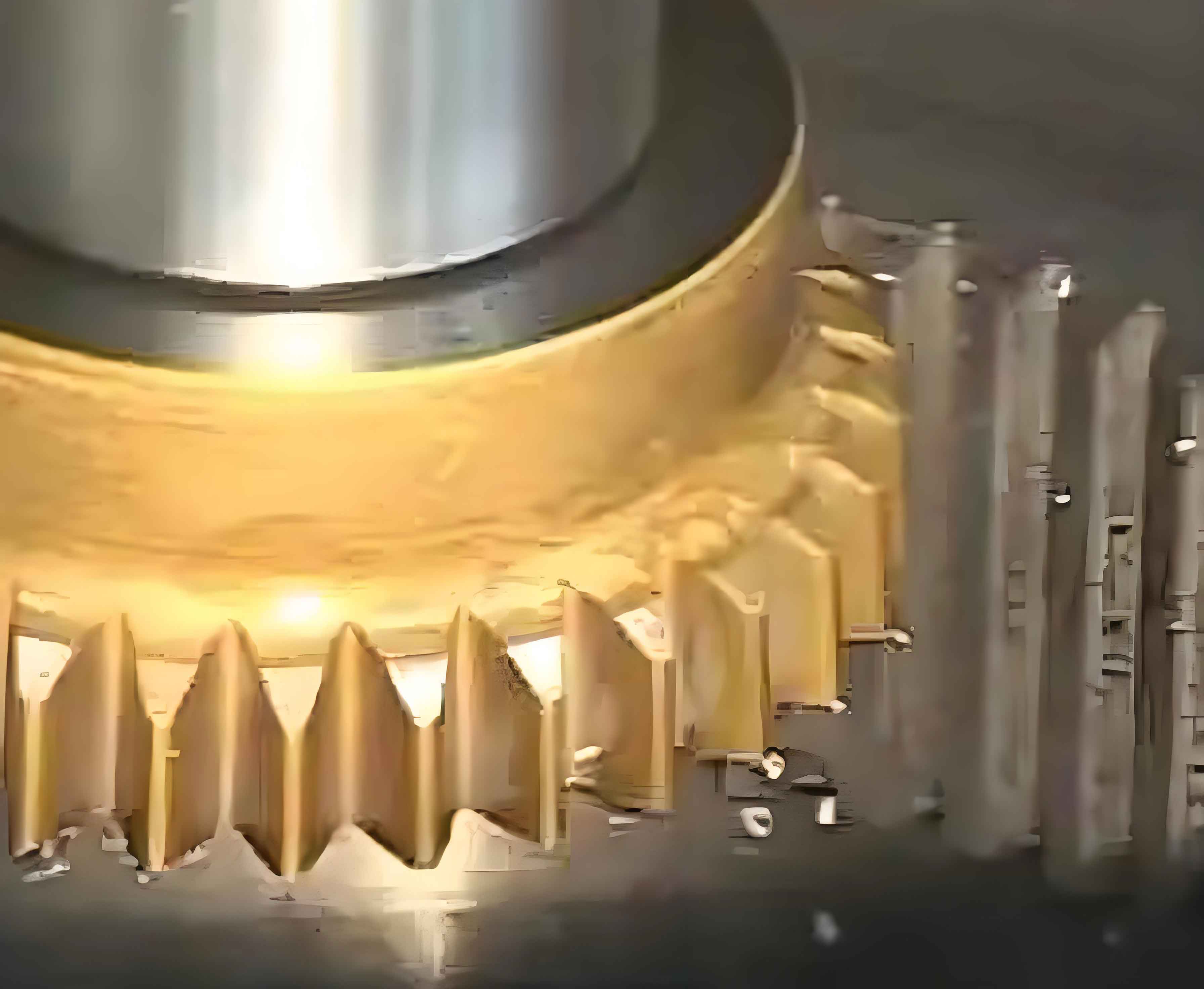
The starting point of my method is the relationship between the theoretical involute and the actual cutting edge of a gear shaping cutter. A gear shaping cutter with front rake and relief does not project a perfect involute onto the reference plane. The cutting edge is displaced along the tooth flank, and the projection therefore differs from the theoretical involute. If I design the cutter profile only from the nominal pressure angle and do not correct this projection error, the internal spline produced by gear shaping will carry a systematic profile deviation. The error is usually small, but it is not negligible for high-speed, high-torque, or long-life spline connections. In my design procedure, I therefore calculate the projection equation of the cutting edge, quantify the profile error at the addendum, dedendum, and base circle, and then correct the end-face pressure angle of the gear shaping cutter so that the tangent at the reference circle approaches the theoretical involute tangent. This correction reduces the theoretical error dramatically and gives the gear shaping process a more reliable starting geometry.
I define the basic involute parameter at an arbitrary radius by the usual relation between pressure angle and radius, and I use the involute function to express the angular coordinate of the tooth flank. The projection of the cutting edge is obtained by combining the involute geometry with the axial displacement caused by the rake angle and the additional angular displacement caused by the helix-like effect of the relief angle. The resulting equations are the basis of my computer-aided gear shaping cutter design.
$$
\theta_y=\operatorname{inv}\alpha_y,\qquad
\cos\alpha_y=\frac{r_{bo}}{r_y}
$$
$$
\operatorname{inv}\alpha_y=\tan\alpha_y-\alpha_y
$$
Here, the subscript y denotes an arbitrary point on the cutting edge, rbo is the base-circle radius of the gear shaping cutter, and ry is the radius of the point under consideration. The axial displacement from the reference plane is proportional to the radius and the front rake angle. I write the axial displacement as follows.
$$
\Delta b=r_y\tan\gamma
$$
The angular shift caused by the projection is then calculated from the axial displacement and the local helix angle. Since the helix angle itself depends on the pressure angle and the relief angle, the angular shift can be written in a very compact form. This compact form is convenient for programming because all terms can be evaluated directly from the cutter parameters.
$$
\Delta\varphi=
\frac{\Delta b\tan\beta_y}{r_y}
=
\frac{\Delta b\tan\beta_o}{r_o}
=
\frac{r_y\tan\gamma\tan\beta_o}{r_o}
$$
$$
\tan\beta_o=\tan\alpha_o\tan\alpha_e
$$
$$
\Delta\varphi=
\frac{r_y\tan\gamma\tan\alpha_o\tan\alpha_e}{r_o}
$$
With this angular shift, I obtain the polar equation of the projected cutting edge. The term that contains the product of the rake angle, relief angle, and end-face pressure angle represents the systematic departure from the ideal involute. I collect this product into a coefficient K so that the projected cutting edge can be evaluated at every radius without repeatedly expanding the same trigonometric products. This is one of the practical advantages of a computer-aided formulation: once K is known, the projected profile, the profile error, and the correction target can all be computed from the same underlying expression.
$$
\theta’_y=\theta_y-\Delta\varphi
=
\operatorname{inv}\alpha_y-r_yK
$$
$$
K=\frac{\tan\gamma\tan\alpha_o\tan\alpha_e}{r_o}
$$
In my error analysis, I compare the projected cutting edge with the theoretical involute after rotating the projected curve so that the two curves coincide at the reference circle. This rotation removes the arbitrary angular datum and leaves only the shape difference. At the addendum, the projected curve and the theoretical involute separate by a circumferential error; at the dedendum, the separation has the opposite sign and a smaller magnitude; at the base circle, the separation reflects the accumulated angular difference over the whole flank. The error at any radius is therefore obtained from the difference between two involute functions and a linear term that comes from the projection coefficient K.
$$
\Delta f_y=
r_y\left[
\left(\operatorname{inv}\alpha_{yo}-\operatorname{inv}\alpha_y\right)
-\left(\operatorname{inv}\alpha_o-\operatorname{inv}\alpha\right)
-\left(r_y-r_o\right)K
\right]
$$
$$
\cos\alpha_{yo}=\frac{r_{bo}}{r_y},\qquad
\cos\alpha_y=\frac{r_b}{r_y}
$$
The addendum error, dedendum error, and base-circle error are obtained by substituting the corresponding radii into the same expression. I always calculate all three because the maximum error is not always at the addendum; depending on the pressure angle, the modification coefficient, and the cutter tooth count, the dedendum or the base region can become critical for the final gear shaping result.
$$
\Delta f_a=
r_a\left[
\left(\operatorname{inv}\alpha_{ao}-\operatorname{inv}\alpha_a\right)
-\left(\operatorname{inv}\alpha_o-\operatorname{inv}\alpha\right)
-\left(r_a-r_o\right)K
\right]
$$
$$
\Delta f_f=
r_f\left[
\left(\operatorname{inv}\alpha_{fo}-\operatorname{inv}\alpha_f\right)
-\left(\operatorname{inv}\alpha_o-\operatorname{inv}\alpha\right)
-\left(r_f-r_o\right)K
\right]
$$
$$
\Delta f_b=
r_b\left[
\operatorname{inv}\alpha_{bo}
-\left(\operatorname{inv}\alpha_o-\operatorname{inv}\alpha\right)
-\left(r_b-r_o\right)K
\right]
$$
The correction strategy I use is to modify the end-face pressure angle of the gear shaping cutter so that the tangent of the projected cutting edge at the reference circle coincides with the tangent of the theoretical involute. This is a local matching condition, but it is very effective because the reference circle is the region that controls the pressure-angle behavior of the tooth pair and because the residual error at the addendum and dedendum is much less sensitive to small tangent corrections than to an uncorrected projection. I express the tangent angle of the projected curve by differentiating the polar equation with respect to the radius. After simplification, the tangent angle at the reference circle leads directly to the corrected end-face pressure angle.
$$
\tan\psi=r_y\frac{d\theta’_y}{dr_y}
$$
$$
\tan\psi=
\tan\alpha_y-\frac{r_y}{r_o}\tan\gamma\tan\alpha_o\tan\alpha_e
$$
$$
\tan\alpha_o=
\frac{\tan\alpha}{1-\tan\gamma\tan\alpha_e}
$$
This corrected end-face pressure angle is the key output of my gear shaping cutter design module. The correction preserves the standard pressure angle at the reference circle of the workpiece while substantially reducing the theoretical profile error caused by the cutter rake and relief. The residual error at the tooth tip and tooth root remains small, and it can be evaluated with the same error formulas after the corrected pressure angle has been inserted. In practical gear shaping, this residual error is usually far below the tolerance band of the internal spline, but I still report it because it provides a quantitative basis for tolerance allocation and for comparison between different cutter designs.
I illustrate the correction with a representative gear shaping cutter. The module is 5 mm, the nominal pressure angle is 20 degrees, the cutter tooth count is 20, the addendum coefficient is 0.75, the dedendum coefficient is 0.5, the modification coefficient is 0.25, the relief angle is 6 degrees, and the front rake angle is 5 degrees. These values are typical of an internal spline cutter in which a positive modification is used to control the tooth thickness and the root clearance. I compute the projected profile before correction, compare it with the theoretical involute, and then repeat the computation after applying the corrected end-face pressure angle.
| Parameter | Symbol | Value | Unit |
|---|---|---|---|
| Module | m | 5 | mm |
| Nominal pressure angle | alpha | 20 | degree |
| Gear shaping cutter tooth count | zo | 20 | teeth |
| Addendum coefficient | ha | 0.75 | dimensionless |
| Dedendum coefficient | hf | 0.5 | dimensionless |
| Modification coefficient | x | 0.25 | dimensionless |
| Relief angle | alpha_e | 6 | degree |
| Front rake angle | gamma | 5 | degree |
The error comparison before and after correction is summarized below. I compute the error in the circumferential direction at the addendum, dedendum, and base circle. The corrected design reduces the addendum error by almost four fifths, reduces the dedendum error by nearly nine tenths, and reduces the base-circle error by about one fifth. The base-circle reduction is smaller because the correction is anchored at the reference circle and the base-circle error contains a contribution from the accumulated angular difference over the full involute; nevertheless, the absolute base-circle error remains small enough for the intended internal spline application.
| Error location | Symbol | Before correction, mm | After correction, mm | Reduction, percent |
|---|---|---|---|---|
| Addendum | Delta fa | 0.01841 | 0.00391 | 78.76 |
| Dedendum | Delta ff | 0.00408 | 0.00049 | 87.99 |
| Base circle | Delta fb | 0.00948 | 0.00758 | 20.04 |
Once the corrected cutter profile is available, I move to interference checking. In gear shaping of internal teeth, the cutter tooth root can enter the non-involute region of the workpiece, and the workpiece tooth tip can be cut by the cutter. This is the well-known top-cutting risk. I check it by comparing the radius at which the internal gear addendum circle intersects the line of action with the radius at which the cutter root begins to participate in the mesh. If the intersection radius is smaller than the critical radius, the gear shaping process will remove material from the gear tip, and the resulting internal spline will have a shortened involute and a disturbed tip region.
$$
K_1O_2\ge A_1O_2
$$
$$
r_{a2}\ge\sqrt{r_{b2}^2+\left(a_{o2}\sin\alpha_{o2}\right)^2}
$$
In the expression above, ra2 is the addendum-circle radius of the internal gear, rb2 is its base-circle radius, ao2 is the center distance used in the interference check, and alpha_o2 is the pressure angle at the operating pitch point. I use this inequality as a hard constraint in my gear shaping cutter design. If the constraint is violated, I adjust the cutter addendum, the modification coefficient, or the workpiece addendum allowance before proceeding to simulation. This is much more efficient than discovering top cutting after a trial cut.
The second check concerns cutting-in interference. During the radial feed of the gear shaping cutter, the cutter tip can remove part of the workpiece addendum corner before the full tooth depth is reached. This phenomenon depends on the relative position of the cutter tip and the workpiece addendum as the cutter enters the internal gear space. In my calculation, I compare the clearance of the cutter tip from the center line with the clearance of the workpiece addendum from the same reference. When the cutter-side clearance is larger than the workpiece-side clearance, material removal at the addendum corner is possible. I therefore evaluate a non-interference margin function and require it to remain non-negative over the entire cutting-in phase.
$$
\Phi=
\arcsin\sqrt{
\frac{
1-\left(\frac{\cos\alpha_{ao}}{\cos\alpha_{a2}}\right)^2
}{
1-\left(\frac{z_o}{z_2}\right)^2
}}
+\operatorname{inv}\alpha_{ao}-\operatorname{inv}\alpha’
-\frac{z_2}{z_o}
\left[
\arcsin\sqrt{
\frac{
\left(\frac{\cos\alpha_{a2}}{\cos\alpha_{ao}}\right)^2-1
}{
\left(\frac{z_o}{z_2}\right)^2-1
}}
+\operatorname{inv}\alpha_{a2}-\operatorname{inv}\alpha
\right]
\ge 0
$$
I keep the full form of this margin function in my gear shaping simulation program because it allows the operator to see how close the design is to the interference boundary. A design that satisfies the inequality but has a very small margin is not robust, especially when cutter wear, re-grinding, or small changes in the workpiece addendum are considered. In my experience, it is better to leave a clear positive margin than to accept a mathematically non-interfering design that is too close to the boundary.
The third classical check is tooth-profile overlap interference. This occurs when the cutter addendum interferes with the internal gear addendum as the cutter exits the tooth space at the end of the mesh cycle. In many internal gear shaping cases, overlap interference is accompanied by cutting-in interference, so a strict cutting-in check already removes most of the risk. I nevertheless keep a separate overlap check in my program for diagnostic purposes, particularly when the cutter has a large tip rounding or when the internal spline has a non-standard addendum. The overlap check is not usually the limiting constraint, but it provides a useful cross-check on the envelope generated by the simulation.
After the cutter profile and interference constraints are established, I compute the mounting center distance. I regard the gear shaping cutter as a modified external gear and the internal spline as an internal gear. The gear shaping process is then represented as a no-backlash internal-external mesh. The working pressure angle at the cutter-workpiece interface is obtained from the involute equation, and the center distance follows from the working pressure angle and the standard center distance. This center distance is used both for the analytical interference checks and for the coordinate transformation in the simulation.
$$
\operatorname{inv}\alpha’_o=
\frac{2\tan\alpha}{z_o+z}\left(x+x_o\right)
+\operatorname{inv}\alpha
$$
$$
a_o=
\frac{m\left(z_o+z\right)}{2}
\frac{\cos\alpha}{\cos\alpha’_o}
$$
In the equations above, zo is the cutter tooth count, z is the workpiece tooth count, x is the workpiece modification coefficient, xo is the cutter modification coefficient, and alpha is the nominal pressure angle. I solve the involute equation iteratively because the working pressure angle appears both directly and inside the involute function. The iteration converges very quickly when the initial value is taken as the nominal pressure angle, and the converged value is then used for the full gear shaping simulation.
| Item | Formula or condition | Purpose in gear shaping design |
|---|---|---|
| Projected cutting edge | theta_y’ = inv alpha_y – r_y K | Defines the actual projected profile of the gear shaping cutter |
| Profile error | Delta f_y = r_y [inv alpha_yo – inv alpha_y – inv alpha_o + inv alpha – (r_y – r_o)K] | Quantifies theoretical error before and after correction |
| Corrected pressure angle | tan alpha_o = tan alpha / (1 – tan gamma tan alpha_e) | Reduces projection error by matching reference-circle tangent |
| Top-cutting check | r_a2 ≥ sqrt(r_b2^2 + (a_o2 sin alpha_o2)^2) | Prevents cutter root from cutting the internal gear tip |
| Cutting-in margin | Phi ≥ 0 | Prevents addendum-corner removal during radial feed |
| Center distance | inv alpha’_o = 2 tan alpha (x + x_o)/(zo + z) + inv alpha | Positions cutter and workpiece for no-backlash mesh |
For the gear shaping process simulation, I use a coordinate transformation that represents the relative motion between the cutter and the internal gear. The cutter rotates about its own center, the internal gear rotates about its center, and the cutter center travels around the internal gear center according to the center distance. Because the simulation is performed in a coordinate system fixed to the internal gear, the cutter appears to rotate by the relative angle between the cutter rotation and the workpiece rotation. This relative angle is the product of the workpiece rotation and the ratio of workpiece tooth count to cutter tooth count, minus the workpiece rotation itself. The resulting transformation is simple enough for direct programming but complete enough to generate an accurate envelope.
$$
\theta_o=\theta\frac{z_2}{z_o}
$$
$$
\delta=\theta_o-\theta
=\theta\left(\frac{z_2}{z_o}-1\right)
$$
I take an arbitrary point M on the cutting edge, expressed in the cutter coordinate system as xm and ym. I convert this point to polar form, subtract the relative rotation angle, and then add the cutter-center position in the workpiece coordinate system. The final coordinates give the position of that cutting-edge point in the internal gear frame at a given workpiece rotation angle. By repeating this calculation for all points on the cutting edge and for a sequence of rotation angles, I obtain the complete family of cutter positions that defines the gear shaping envelope.
$$
R_m=\sqrt{x_m^2+y_m^2}
$$
$$
\phi_m=\arcsin\frac{x_m}{R_m}
$$
$$
x’_m=R_m\sin\left(\phi_m-\delta\right)
$$
$$
y’_m=R_m\cos\left(\phi_m-\delta\right)
$$
$$
x’_o=a_o\sin\theta
$$
$$
y’_o=a_o\cos\theta
$$
$$
x”_m=x’_m+a_o\sin\theta
$$
$$
y”_m=y’_m+a_o\cos\theta
$$
The envelope of the gear shaping cutter is the boundary of the union of all cutter positions. I do not need to calculate the union analytically; I generate the cutter profile at a sufficiently fine angular step, transform each profile into the workpiece frame, and then extract the envelope from the resulting curve family. The envelope represents the actual tooth surface produced by gear shaping. The involute portion of the envelope should coincide with the theoretical involute, while the root region contains the transition curve generated by the cutter tip. The extent of the involute portion is the key result for spline matching because it determines the maximum addendum diameter that the mating external spline may have without transition-curve interference.
$$
\mathcal{E}(\theta)=
\bigcup_{\theta\in[\theta_1,\theta_2]}
\Gamma_o(\theta)
$$
I implement the transformation in a Visual Basic program that writes an AutoCAD script file. The script contains the polyline or spline commands for each cutter position. When the script is executed, the cutter profiles appear as a dense curve family, and the envelope is visible as the smooth boundary of that family. This approach is lightweight, transparent, and easy to verify because every transformed point can be traced back to a cutter-edge point and a workpiece rotation angle. I use a small angular step near the final tooth flank and a larger step in the non-cutting region so that the simulation remains fast without sacrificing envelope accuracy.
| Simulation input | Symbol | Value | Unit |
|---|---|---|---|
| Module | m | 5 | mm |
| Pressure angle | alpha | 20 | degree |
| Internal gear tooth count | z2 | 45 | teeth |
| Internal gear addendum coefficient | ha2 | 0.5 | dimensionless |
| Internal gear dedendum coefficient | hf2 | 0.75 | dimensionless |
| Internal gear modification coefficient | x2 | 0 | dimensionless |
| Gear shaping cutter tooth count | zo | 20 | teeth |
| Gear shaping cutter modification coefficient | xo | 0.25 | dimensionless |
For the representative internal spline, the simulation gives a maximum involute diameter of 230.712 mm. The tooth tip circle of the internal gear is 232.5 mm, and the root circle is 220 mm. This means that the involute portion of the internal spline extends from the root region up to a diameter of 230.712 mm, while the tooth tip region from 230.712 mm to 232.5 mm is not usable involute. If the mating external spline has an addendum circle larger than 230.712 mm, the external spline tip will contact the transition curve of the internal spline instead of the involute flank. This is exactly the transition-curve interference that I want to prevent in gear shaping design. The simulation therefore provides a direct design instruction: the external spline addendum must be kept below the simulated maximum involute diameter, or the internal spline cutter and workpiece addendum must be modified to extend the involute portion.
| Envelope result | Value | Unit | Design significance |
|---|---|---|---|
| Internal gear tip-circle diameter | 232.5 | mm | Overall radial boundary of the internal tooth space |
| Maximum involute diameter | 230.712 | mm | Upper limit for mating external spline addendum |
| Internal gear root-circle diameter | 220 | mm | Lower radial boundary of the internal tooth space |
I validated the simulation with an actual gear shaping trial. The internal spline material was 42CrMoA, quenched and tempered to a hardness range of 280 to 310 HB. The gear shaping cutter was made of S390 powder-metallurgy high-speed steel. After gear shaping, the tooth profile was measured, and the measured involute start diameter was 230.71 mm. This agrees with the simulated maximum involute diameter of 230.712 mm to within the measurement resolution. The agreement confirms that the coordinate transformation, the center-distance calculation, and the envelope extraction are consistent with the actual gear shaping kinematics. It also confirms that the transition curve observed on the finished part is not a random grinding artifact but a predictable result of the gear shaping cutter tip geometry and the relative motion.
| Validation item | Specification or result |
|---|---|
| Workpiece material | 42CrMoA |
| Heat treatment | Quenched and tempered |
| Hardness range | 280 to 310 HB |
| Gear shaping cutter material | S390 powder-metallurgy high-speed steel |
| Simulated maximum involute diameter | 230.712 mm |
| Measured involute start diameter | 230.71 mm |
| Agreement | Within measurement resolution |
From my perspective, the most important outcome of this work is not a single cutter drawing but a repeatable gear shaping design workflow. I first define the workpiece geometry and the internal spline requirements. I then calculate the uncorrected gear shaping cutter profile, evaluate the projection error caused by rake and relief, and apply the corrected end-face pressure angle. I check top cutting, cutting-in interference, and overlap interference using closed-form inequalities. I compute the no-backlash center distance and generate the full gear shaping envelope. Finally, I extract the maximum involute diameter and use it as a constraint on the mating external spline. This workflow turns gear shaping from a trial-and-error process into a predictable design process.
| Step | Activity | Key output | Gear shaping benefit |
|---|---|---|---|
| 1 | Define workpiece and cutter parameters | Module, pressure angle, tooth counts, coefficients | Establishes the gear shaping design space |
| 2 | Calculate projected cutting edge | Theta_y’ and coefficient K | Reveals the true cutting-edge projection |
| 3 | Evaluate profile error | Addendum, dedendum, base-circle errors | Quantifies theoretical gear shaping error |
| 4 | Correct end-face pressure angle | Corrected alpha_o | Reduces gear shaping profile deviation |
| 5 | Check interference | Top-cutting and cutting-in margins | Prevents unacceptable gear shaping defects |
| 6 | Compute center distance | a_o and working pressure angle | Positions cutter for accurate gear shaping |
| 7 | Simulate envelope | Maximum involute diameter | Guides external spline addendum design |
| 8 | Validate by measurement | Measured involute start diameter | Confirms gear shaping simulation accuracy |
I also use the error formulas as a sensitivity tool. When the front rake angle increases, the projection error tends to increase because the axial displacement of the cutting edge becomes larger. When the relief angle increases, the angular shift caused by the effective helix also changes, and the corrected end-face pressure angle moves away from the nominal value. The correction formula shows this coupling explicitly: the denominator contains the product of the tangent of the rake angle and the tangent of the relief angle. This is why I do not treat rake and relief as independent tool-grinding details. In gear shaping, they are part of the profile-generation system, and they must be included in the cutter design from the beginning.
$$
\frac{\partial}{\partial\gamma}
\left(\tan\alpha_o\right)
=
\frac{\tan\alpha\tan\alpha_e}
{\left(1-\tan\gamma\tan\alpha_e\right)^2}
$$
$$
\frac{\partial}{\partial\alpha_e}
\left(\tan\alpha_o\right)
=
\frac{\tan\alpha\tan\gamma}
{\left(1-\tan\gamma\tan\alpha_e\right)^2}
$$
The sensitivity equations above show that the corrected pressure angle is more sensitive to the relief angle when the rake angle is large, and more sensitive to the rake angle when the relief angle is large. In practical cutter grinding, this means that a change in the relief grinding specification can shift the effective profile even if the front rake is unchanged. I therefore record the actual rake and relief angles after grinding and use them in the final gear shaping simulation rather than relying only on the nominal drawing values.
Another practical point is the treatment of the cutter tip rounding. A real gear shaping cutter does not end in a perfectly sharp corner; the tip is rounded to reduce stress concentration and to improve tool life. This rounding enlarges the transition-curve radius at the root of the internal spline and reduces the maximum involute diameter compared with an ideal sharp-tip simulation. In my current envelope model, I can include the tip rounding by replacing the sharp tip with a circular arc and transforming the arc together with the involute flank. The resulting envelope is slightly shorter in the involute region, and the mating external spline addendum must be reduced accordingly. This effect is important for splines that operate near the transition-curve boundary, and I treat it as a separate refinement of the basic gear shaping simulation.
The same simulation framework can be extended to asymmetric tooth profiles, tapered internal splines, and cutters with protuberance. For an asymmetric profile, the left and right flanks have different pressure angles, so I generate two independent envelope families and combine them at the tooth center. For a tapered internal spline, the center distance and the axial position change along the part, so I perform the envelope calculation at several axial sections and interpolate the maximum involute diameter between them. For a protuberance cutter, the tip region is modified to control the root fillet, and the envelope must include both the involute-generating portion and the protuberance portion. These extensions all rely on the same gear shaping coordinate transformation and the same interference-checking logic.
| Extension | Additional input | Simulation change | Gear shaping application |
|---|---|---|---|
| Asymmetric profile | Separate left and right pressure angles | Two envelope families | Asymmetric internal splines |
| Tapered spline | Axial taper and section positions | Multi-section envelope | Tapered internal tooth connections |
| Protuberance cutter | Protuberance amount and tip geometry | Combined involute and tip envelope | Root fillet control in gear shaping |
| Tip rounding | Tip radius | Arc-based envelope | Tool-life improvement and transition control |
I pay particular attention to the definition of the maximum involute diameter because it is the link between gear shaping simulation and spline assembly. The internal spline produced by gear shaping has a usable involute region that begins at the transition curve and ends near the tooth tip. The external spline has an addendum circle that must not reach the transition curve. If the external spline addendum is too large, the contact moves onto the non-involute transition region, the effective contact ratio changes, and the local contact stress increases. In a deep-hole internal spline, this problem is difficult to inspect after assembly, so the design must be correct before gear shaping. My simulation provides the maximum allowable external spline addendum diameter directly from the envelope, and I use this value as a design constraint in the spline matching calculation.
The interference checks and the envelope simulation are complementary. The analytical top-cutting check tells me whether the cutter root will cut the workpiece tip at a single critical position. The cutting-in margin tells me whether the cutter tip will remove the workpiece addendum corner during radial feed. The envelope simulation tells me the final shape of the tooth space after the complete gear shaping motion, including the transition curve and the extent of the involute. I use all three because each addresses a different failure mode. A design that passes the analytical checks can still have a short involute region, and a design that has a long involute region can still suffer from cutting-in interference if the radial feed path is not controlled. The complete gear shaping design therefore requires both closed-form checking and numerical simulation.
| Check | Failure mode addressed | Output | Action if violated |
|---|---|---|---|
| Top-cutting inequality | Cutter root cuts internal gear tip | Radius margin | Reduce cutter addendum or change modification |
| Cutting-in margin | Addendum corner removed during feed | Phi value | Adjust cutter tip or feed strategy |
| Overlap check | Cutter tip interferes at exit | Overlap indicator | Modify tip rounding or tooth counts |
| Envelope simulation | Short involute or transition interference | Maximum involute diameter | Limit mating spline addendum or redesign cutter |
In my computer-aided design environment, I store the cutter parameters, the workpiece parameters, the calculated correction angle, the error table, the interference margins, and the envelope result in a single design record. This record becomes the traceability document for the gear shaping tool. If a cutter is re-ground, I update the rake angle, relief angle, and tooth thickness, and the program recalculates the corrected pressure angle and the envelope. If the workpiece heat treatment changes the addendum allowance, I update the workpiece parameters and recheck the maximum involute diameter. This traceability is valuable because gear shaping cutters are re-ground many times, and each re-grind changes the effective profile. A design that is correct only for the new cutter may become marginal after several re-grinds if the correction and interference margins are not tracked.
I also use the gear shaping simulation to communicate with manufacturing. Instead of giving the shop only a cutter drawing, I provide an envelope plot with the maximum involute diameter, the root diameter, and the tip diameter marked. The shop can then see why a particular external spline addendum limit is specified. This reduces the risk that a supplier will treat the addendum limit as an arbitrary tolerance. In internal spline production, the transition curve is often the hidden variable that causes assembly problems, and a visual envelope makes that variable visible. The gear shaping simulation therefore has both a technical and a communication function.
Looking at the numerical results, the corrected gear shaping cutter reduces the addendum error from 0.01841 mm to 0.00391 mm, the dedendum error from 0.00408 mm to 0.00049 mm, and the base-circle error from 0.00948 mm to 0.00758 mm. These values are small in absolute terms, but their ratio matters. The addendum error reduction of about 79 percent and the dedendum error reduction of about 88 percent mean that the cutter profile is much closer to the theoretical involute over the region that controls the mesh. The base-circle error reduction is smaller, but the base-circle region is not the primary contact region for most internal splines. I therefore regard the correction as successful for the intended gear shaping application, while keeping the residual base-circle error in the tolerance analysis.
The experimental measurement of 230.71 mm for the involute start diameter is a strong confirmation of the simulation. The simulated value is 230.712 mm, and the difference is only 0.002 mm. In a production environment, this level of agreement is more than sufficient because the measurement uncertainty and the cutter manufacturing tolerance are of the same order or larger. The agreement also shows that the no-backlash center distance and the relative rotation transformation are correct. If either the center distance or the rotation ratio were wrong, the envelope would shift, and the maximum involute diameter would deviate from the measured value. The fact that the two values coincide gives me confidence in the gear shaping model.
| Quantity | Analytical or simulated value | Measured value | Difference |
|---|---|---|---|
| Maximum involute diameter | 230.712 mm | 230.71 mm | 0.002 mm |
| Internal gear tip diameter | 232.5 mm | Within drawing tolerance | Not applicable |
| Internal gear root diameter | 220 mm | Within drawing tolerance | Not applicable |
I conclude that a computer-aided gear shaping design should always include four elements. The first is a projection model of the cutting edge that accounts for rake and relief. The second is a pressure-angle correction that reduces the theoretical profile error. The third is a set of interference checks that covers top cutting and cutting-in interference. The fourth is a kinematic simulation that generates the envelope and identifies the maximum involute diameter. When these four elements are combined, gear shaping becomes a predictable process, and the internal spline design can be matched to the external spline before any metal is cut. This is the approach I use for deep-hole internal splines, and it is the reason I place gear shaping simulation at the center of my cutter design workflow.
In future work, I plan to refine the envelope model by including the exact tip rounding of the gear shaping cutter, the wear-induced change in rake angle, and the elastic deflection of the cutter arbor. These effects are secondary compared with the projection error and the interference margins, but they become important when the spline tolerance is tight or when the cutter is used near the end of its regrind life. I also plan to automate the search for the cutter modification coefficient that maximizes the involute extent while keeping the cutting-in margin positive. This would turn the current design procedure into an optimization loop and further strengthen the role of gear shaping simulation in internal spline manufacturing.
| Design aspect | Current practice | Planned refinement | Expected gear shaping benefit |
|---|---|---|---|
| Tip geometry | Sharp-tip approximation | Exact tip arc envelope | More accurate transition curve |
| Cutter wear | Nominal rake and relief | Regrind-dependent angles | Better profile control over tool life |
| Arbor deflection | Rigid kinematic model | Elastic compensation | Improved depth and profile consistency |
| Modification search | Manual iteration | Automated optimization | Maximum involute extent with positive margin |
My overall assessment is that gear shaping of internal splines is controlled by geometry rather than by force or speed alone. The cutter profile, the rake and relief angles, the center distance, the relative rotation, and the tip geometry all combine to produce the final tooth space. If any one of these is treated as a minor detail, the result can be a profile error, a short involute, or a transition-curve interference that is difficult to correct after heat treatment. By using the projection equations, the corrected pressure angle, the interference inequalities, and the envelope simulation together, I can design a gear shaping cutter that is accurate, robust, and traceable. The measured result confirms that the simulation is not merely a graphical exercise; it predicts the actual involute start diameter within a few thousandths of a millimeter. This is the standard I apply to gear shaping cutter design for internal splines.