
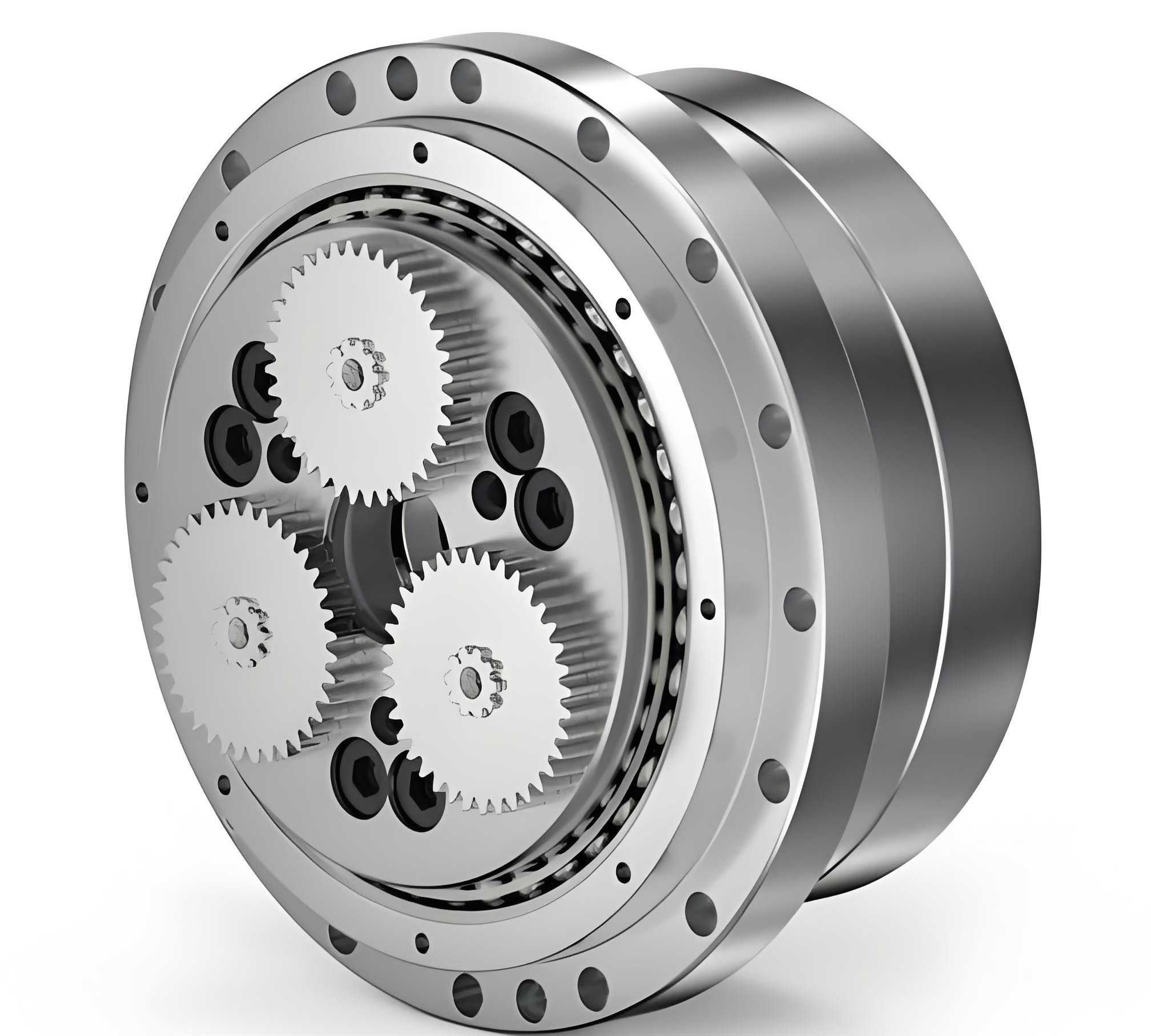
The rotary vector reducer, a high-precision planetary transmission device, has become a cornerstone in advanced robotics and automation due to its exceptional characteristics: compact size, high torque density, high reduction ratio, and excellent torsional stiffness. At the heart of its two-stage reduction mechanism lies the cycloid-pin gear pair, which is primarily responsible for the device’s superior load-bearing capacity and precision. The performance, longevity, and noise-vibration characteristics of the rotary vector reducer are critically dependent on the meshing quality of this cycloid drive.
In an ideal theoretical model, a standard cycloid profile meshes with pin teeth without any clearance. However, practical implementation necessitates profile modification. Lubrication requires an oil film gap, manufacturing errors must be compensated for, and assembly demands operational clearance. Therefore, intentional deviation from the theoretical profile—known as profile modification—is essential. The challenge lies in performing this modification in a way that simultaneously ensures high transmission accuracy (minimal backlash variation) and maintains optimal load distribution across multiple teeth to preserve the inherent high load capacity of the rotary vector reducer. An improper modification strategy can lead to increased vibration, noise, premature wear, and reduced positional accuracy, negating the advantages of this sophisticated transmission system.
Fundamentals of Cycloid Gear Generation and Modification Methods
The standard cycloid tooth profile is generated by a hypocycloid principle. As a rolling circle of radius $r_r’$ rotates without slippage around a fixed base circle of radius $r_p’$, a point on the periphery of the rolling circle traces an epicycloid. A point at a fixed distance from the center of the rolling circle traces a curtate epicycloid, which forms the working flank of the cycloid gear. The parametric equations for the standard cycloid gear profile, relative to its own center, are given by:
$$
\begin{aligned}
x_c &= \left[ r_p – r_{rp} \, s^{-1/2} \right] \cos\left[ (1 – i^H) \phi \right] – \frac{a}{r_p} \left[ r_p – z_p r_{rp} \, s^{-1/2} \right] \cos(i^H \phi) \\
y_c &= \left[ r_p – r_{rp} \, s^{-1/2} \right] \sin\left[ (1 – i^H) \phi \right] + \frac{a}{r_p} \left[ r_p – z_p r_{rp} \, s^{-1/2} \right] \sin(i^H \phi)
\end{aligned}
$$
where:
$z_p$ is the number of pin teeth (and $z_p = z_c + 1$, with $z_c$ being the number of cycloid gear teeth),
$s = 1 + k_1^2 – 2k_1 \cos \phi$,
$k_1$ is the shortening coefficient, $k_1 = a z_p / r_p$,
$i^H$ is the transmission ratio, $i^H = z_p / z_c$,
$a$ is the eccentricity,
$r_{rp}$ is the pin tooth (or generating grinding wheel) radius,
$r_p$ is the pitch radius of the pin circle.
The parameter $\phi$ is the generating angle.
In practical manufacturing, the cycloid gear is ground by a disc-shaped grinding wheel. Modification is achieved by strategically altering the relative position or size of this grinding wheel during the finishing process. The primary independent modification methods are:
- Offset Modification ($\Delta r_{rp}$): This involves changing the radius of the grinding wheel. A negative offset (reducing the wheel radius) results in a profile that is inwardly offset from the standard curve, creating clearance. The shortening coefficient remains unchanged.
- Center Distance Modification ($\Delta r_p$): This involves altering the center distance between the grinding wheel and the cycloid gear blank. A positive modification (increasing the distance) changes the shortening coefficient to $k_1′ = a z_p / (r_p + \Delta r_p)$ and generates a different curtate epicycloid with inherent clearance.
- Rotation Angle Modification ($\delta$): This is considered the ideal theoretical modification. It involves rotating the cycloid gear blank relative to the grinding wheel by a small angle $\delta$ during generation. This produces a profile with nearly constant angular backlash, which is optimal for smooth operation and load distribution. However, it is complex and costly to implement accurately on standard grinding machines.
- Tooth Thickness Modification ($\Delta f$): This is a post-grinding operation where the grinding wheel is fed laterally to remove additional material from both sides of the tooth, symmetrically reducing tooth thickness.
Among these, rotation angle modification yields the best theoretical meshing characteristics but is impractical for standard production. The common industrial approach has been to use a combination of negative offset and positive center distance modification to approximate its effects. However, this two-parameter combination often fails to achieve a sufficiently close fit to the ideal rotation-modified profile, leading to compromises in either precision or load capacity. The tooth thickness modification parameter is often ignored in optimization models, yet it provides an additional degree of freedom to better approximate the ideal profile.
Mathematical Model for Composite Profile Modification
To bridge the gap between ideal performance and practical manufacturability, we propose a composite modification method based on three easily controllable parameters: Offset ($\Delta r_{rp}$), Center Distance ($\Delta r_p$), and Tooth Thickness ($\Delta f$) modification. This model intentionally excludes rotation angle modification and treats “tooth height modification” as an effect already captured by center distance modification, thereby simplifying the optimization search space while enhancing fitting capability.
The mathematical model is built by sequentially applying the coordinate transformations of each modification to the standard profile. The profile after applying offset and center distance modifications is derived by substituting $r_{rp} \rightarrow (r_{rp} + \Delta r_{rp})$ and $r_p \rightarrow (r_p + \Delta r_p)$ into the standard equations, and updating the shortening coefficient accordingly:
$$
\begin{aligned}
x_a &= \left[ (r_p + \Delta r_p) – (r_{rp} + \Delta r_{rp}) \, {s’}^{-1/2} \right] \cos\left[ (1 – i^H) \phi \right] \\
&- \frac{a}{r_p + \Delta r_p} \left[ r_p + \Delta r_p – z_p (r_{rp} + \Delta r_{rp}) \, {s’}^{-1/2} \right] \cos(i^H \phi) \\
y_a &= \left[ (r_p + \Delta r_p) – (r_{rp} + \Delta r_{rp}) \, {s’}^{-1/2} \right] \sin\left[ (1 – i^H) \phi \right] \\
&+ \frac{a}{r_p + \Delta r_p} \left[ r_p + \Delta r_p – z_p (r_{rp} + \Delta r_{rp}) \, {s’}^{-1/2} \right] \sin(i^H \phi)
\end{aligned}
$$
where $s’ = 1 + {k’_1}^2 – 2k’_1 \cos \phi$ and $k’_1 = a z_p / (r_p + \Delta r_p)$.
The tooth thickness modification is applied as a final normal direction adjustment to the profile defined by $(x_a, y_a)$. The comprehensive model for a point $M$ on the composite-modified profile is:
$$
\boxed{
\begin{aligned}
x &= x_a + k’_1 \Delta f \, {s’}^{-1} \left\{ k’_1 \cos(i^H \phi) – \cos\left[ (1 – i^H) \phi \right] \right\} \\
y &= y_a + k’_1 \Delta f \, {s’}^{-1} \left\{ k’_1 \sin(i^H \phi) – \sin\left[ (1 – i^H) \phi \right] \right\}
\end{aligned}
}
$$
This model $M(\phi; \Delta r_p, \Delta r_{rp}, \Delta f)$ has three independent variables, providing greater flexibility to approximate the ideal rotation-modified profile $M_1(\phi; \delta)$ compared to traditional two-variable models. The objective is to find the optimal triplet $(\Delta r_p^*, \Delta r_{rp}^*, \Delta f^*)$ that minimizes the difference between $M$ and $M_1$.
Optimization Design for the Composite Modification
Design Variables and Objective Function
Since offset and center distance modifications are linked by the requirement to achieve a specific total radial clearance $\Delta a$ (to compensate for machining errors and ensure assembly), we have $\Delta r_p + \Delta r_{rp} = \Delta a$. Following best practices for the rotary vector reducer to ensure good load-bearing capacity and lubrication, we adopt a negative offset and positive center distance combination. Therefore, $\Delta r_{rp} < 0$ and $\Delta r_p > 0$.
Consequently, the independent design variables for optimization are chosen as:
$$
\mathbf{X} = \begin{bmatrix} x_1 \\ x_2 \end{bmatrix} = \begin{bmatrix} \Delta r_{rp} \\ \Delta f \end{bmatrix}
$$
where $\Delta r_p = \Delta a – \Delta r_{rp}$.
The ideal rotation-modified profile $M_1$ is given by:
$$
\begin{aligned}
x_1 &= \left( r_p – r_{rp} s^{-1/2} \right) \cos\left[ (1 – i^H) \phi – \delta \right] – \frac{a}{r_p} \left( r_p – z_p r_{rp} s^{-1/2} \right) \cos(i^H \phi + \delta) \\
y_1 &= \left( r_p – r_{rp} s^{-1/2} \right) \sin\left[ (1 – i^H) \phi – \delta \right] + \frac{a}{r_p} \left( r_p – z_p r_{rp} s^{-1/2} \right) \sin(i^H \phi + \delta)
\end{aligned}
$$
The optimal rotation angle $\delta$ is determined based on the maximum anticipated machining error $\Delta L$ across the entire profile. The required compensation angle varies with $\phi$: $\delta_i = \Delta L / (a z_c \sin \phi_i \cdot s^{-1/2})$. The value $\delta$ used in optimization is typically the extreme value from this distribution that ensures sufficient clearance.
The objective is to minimize the geometric deviation between the composite-modified profile $M$ and the ideal rotation-modified profile $M_1$. A least-squares fitting approach over $m$ discrete points along the profile is used. The objective function is:
$$
\min f(\Delta r_{rp}, \Delta f) = \frac{1}{m} \sum_{i=1}^{m} \left\| M_1(\phi_i) – M(\phi_i; \Delta r_{rp}, \Delta f) \right\|^2
$$
where $ \left\| M_1 – M \right\| = \sqrt{ (x_1 – x)^2 + (y_1 – y)^2 } $.
Constraints
The optimization is subject to the following constraints:
1. Radial Clearance Constraint: $\Delta r_p + \Delta r_{rp} = \Delta a$.
2. Modification Direction Constraint: $\Delta r_{rp} < 0$ (implies $\Delta r_p > \Delta a$).
3. Tooth Thickness Bound: $|\Delta f| \le \Delta s$, where $\Delta s$ is a practical limit based on tooth strength.
This constrained nonlinear optimization problem can be efficiently solved using algorithms such as sequential quadratic programming (SQP) or interior-point methods available in computational tools like MATLAB.
Design Instance and Comparative Analysis
To validate the proposed composite modification method, we apply it to a PFT255-type rotary vector reducer. The key design parameters are listed below:
| Parameter | Symbol | Value | Unit |
|---|---|---|---|
| Number of Cycloid Gear Teeth | $z_c$ | 39 | – |
| Number of Pin Teeth | $z_p$ | 40 | – |
| Pin Circle Radius | $r_p$ | 60.0 | |
| Pin Tooth Radius | $r_{rp}$ | 3.5 | mm |
| Eccentricity | $a$ | 1.2 | mm |
| Target Radial Clearance | $\Delta a$ | 0.0084 | mm |
| Target Rotation Angle | $\delta$ | 0.0004 | rad |
The optimization was performed with a search step of 0.00001 mm for modification values and an angular resolution of $\pi/360$ rad. The tooth thickness modification bound $\Delta s$ was set to $\pm0.5$ mm. The results for the proposed composite modification and several traditional methods are compared in the table below. The fitting error $s$ is the root-mean-square deviation from the ideal rotation-modified profile.
| Modification Method | $\Delta r_p$ (mm) | $\Delta r_{rp}$ (mm) | $\Delta f$ (mm) | Fitting Error $s$ (mm) |
|---|---|---|---|---|
| Proposed Composite | 0.01290 | -0.00450 | 0.01300 | 0.00933 |
| Negative Offset + Positive Center Distance | 0.00841 | -0.00001 | 0 | 0.02564 |
| Offset Only | 0 | 0.00840 | 0 | 0.02115 |
| Center Distance Only | 0.00840 | 0 | 0 | 0.02564 |
| Positive Offset + Positive Center Distance | 0.00082 | 0.00758 | 0 | 0.02109 |
The results are conclusive. The proposed three-parameter composite modification reduces the fitting error to 0.00933 mm, which is 2.26 times smaller than the best traditional two-parameter combination (Positive Offset + Positive Center Distance, error = 0.02109 mm) and 2.75 times smaller than the common Negative Offset + Positive Center Distance approach. This demonstrates a significant enhancement in geometric precision when approximating the ideal rotation-modified profile, a critical factor for the quiet and precise operation of the rotary vector reducer.
Analysis of Meshing Performance
Superior geometric fitting is not the only merit. The performance of a rotary vector reducer under load is dictated by the initial clearance distribution and the resulting load-sharing among teeth. The initial clearance $\Delta(\phi_i)$ for a given tooth $i$ is the normal distance between the modified cycloid flank and the pin tooth at the no-load condition. Under an applied torque, the cycloid gear and pins undergo elastic deformation $\delta_i$. Effective load sharing occurs only for teeth where $\delta_i \ge \Delta(\phi_i)$.
The composite modification, with its optimized parameters, produces a more favorable initial clearance distribution compared to the standard two-parameter modification. Specifically:
- Assembly Friendly: The clearance is adequately sized and smoothly distributed, preventing jamming during the assembly of the cycloid discs, crankshaft, and pin housing.
- Optimal Load Zone: The distribution ensures that a near-optimal number of teeth (typically 1/3 of $z_p$) enter the load-bearing zone simultaneously when deformed. This maximizes the contact ratio and load capacity.
- Reduced Stress Fluctuation: A smooth transition of teeth into and out of the load zone minimizes abrupt changes in contact stress, reducing the risk of pitting fatigue and contributing to longer service life.
- Improved Efficiency: A well-defined, continuous meshing region with minimal “dead-band” backlash variation leads to smoother motion transfer and higher mechanical efficiency.
Practical validation on the PFT255 rotary vector reducer confirmed these theoretical advantages. Gears manufactured with the composite modification assembled seamlessly. Operational testing showed a marked reduction in noise levels from approximately 75 dB to 65 dB. Furthermore, the maximum smooth operating speed increased from about 1000 rpm (with un-optimized modification) to 1200 rpm, with noticeably less vibration. This directly translates to higher performance and reliability in robotic joint applications.
Conclusion and Discussion
This analysis presents a comprehensive and practical framework for optimizing the tooth profile modification of cycloid gears in rotary vector reducers. By formulating a composite modification model that integrates offset, center distance, and tooth thickness modifications, we bridge the gap between the ideal but impractical rotation modification and the limitations of conventional two-parameter methods.
The key findings are:
- The three-degree-of-freedom model provides a vastly superior fit to the ideal profile, with fitting errors reduced by a factor of 2.3 to 2.8 compared to standard methods.
- The optimization process, constrained by practical manufacturing and assembly rules (negative offset, positive center distance, total radial clearance), yields parameters that are directly applicable on standard grinding machines.
- The resulting profile guarantees not only high kinematic precision (minimal and consistent backlash) but also promotes optimal load distribution across multiple teeth, preserving the hallmark high torque density and longevity of the rotary vector reducer.
- Experimental evidence from assembly and run-in tests confirms tangible improvements in smoothness, noise reduction, and maximum operational speed.
The proposed methodology offers a significant tool for designers and manufacturers of precision reducers. Future work could involve integrating this geometric optimization with full elastohydrodynamic lubrication (EHL) analysis and dynamic modeling to create a multi-objective optimization framework for the complete rotary vector reducer system, further pushing the boundaries of its performance in next-generation robotics and precision machinery.