
The pursuit of higher performance, efficiency, and noise reduction in modern machinery has placed increasingly stringent demands on the quality of gear components. Achieving superior surface finish, geometric accuracy, and favorable surface integrity are paramount for enhancing load-carrying capacity, fatigue life, and acoustic behavior. Among various finishing techniques, gear honing has emerged as a critical and efficient process, particularly valued in high-volume industries like automotive manufacturing for its ability to generate a specific, noise-dampening surface texture while improving geometric accuracy. This article delves into the mechanistic modeling and experimental validation of surface roughness generation in a specific variant of this process: internal gear honing.
Surface roughness, typically quantified by parameters such as Ra (arithmetical mean height) or Rz (maximum height of profile), is not merely an aesthetic property. It directly influences functional characteristics including friction, wear, lubrication retention, contact fatigue resistance, and ultimately, the operational lifespan of the gear pair. Therefore, the ability to predict and control surface roughness during gear honing is of immense practical significance. This work focuses on establishing a mathematical model to predict the roughness profile across the tooth flank in internal gear honing processes and analyzes the underlying factors governing its variation.
Theoretical Foundation of Gear Honing
Gear honing is an abrasive finishing process where a honing tool, analogous to a gear, meshes with the workpiece gear under controlled conditions. The honing wheel, typically made of a phenolic resin bond impregnated with abrasive grains (like aluminum oxide or CBN), performs a grinding action through the relative motion between the two gears. The process can be classified into three main types: external gear honing, internal gear honing, and worm-wheel gear honing. Our focus is on internal gear honing, where the honing tool is an internal helical gear. The crossed-axes arrangement between the workpiece and the honing wheel generates a sliding velocity along the tooth profile, which is essential for the cutting action of the abrasive grains.
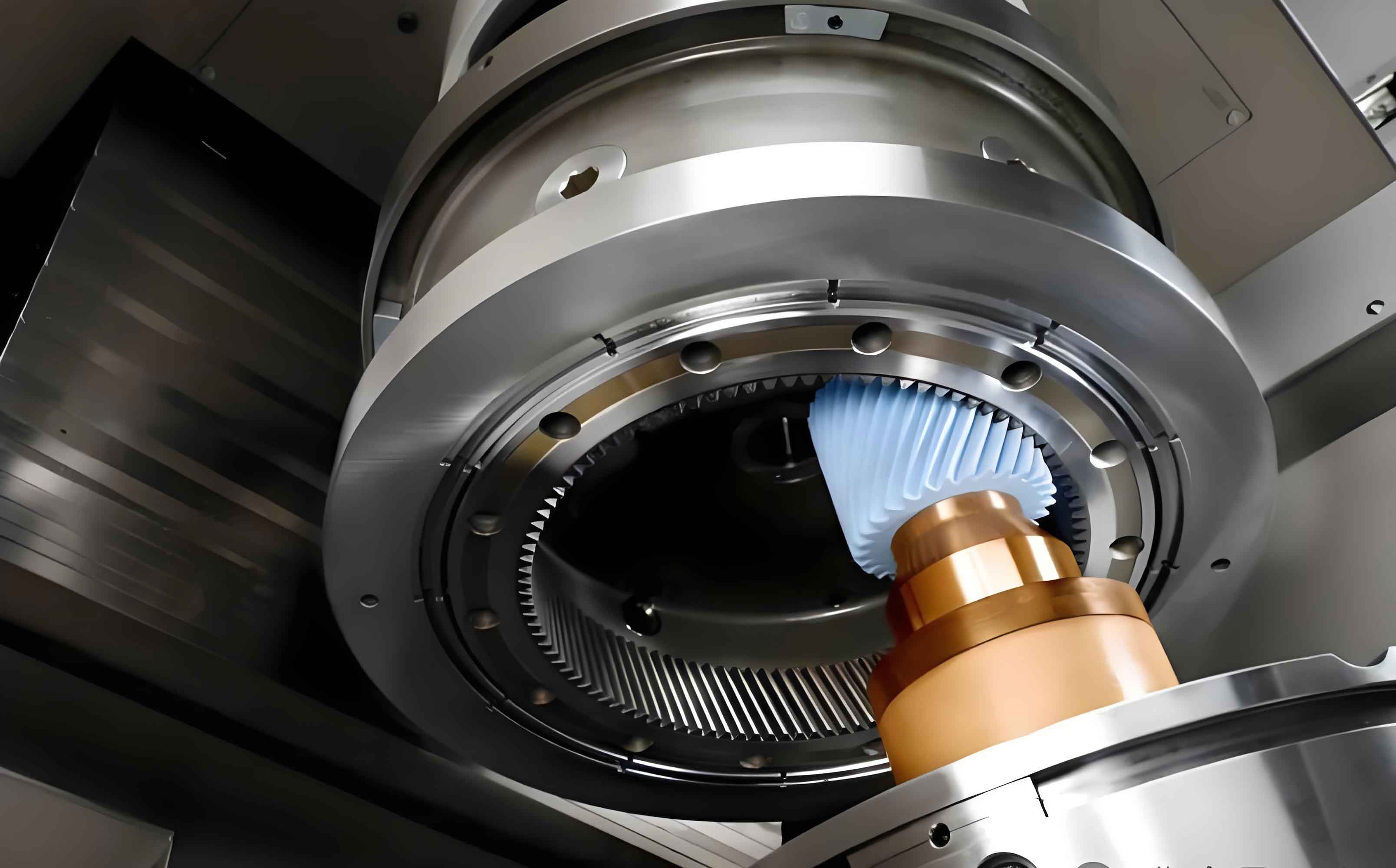
The fundamental mechanism of material removal in gear honing mirrors that of grinding. Countless irregular abrasive grains on the honing wheel’s surface act as microscopic cutting tools. Each grain engages with the workpiece material, performing a complex interaction involving cutting, plowing, and rubbing. The resultant surface topography is a superimposition of the trajectories left by these individual grains. Predicting this final topography requires an understanding of: 1) the kinematics of the honing process, defining the relative motion at any point of contact, and 2) the cutting mechanics of a single abrasive grain, often described by classical grinding theories.
Kinematic Modeling of the Honing Process
To establish the surface roughness model, we first analyze the kinematics of the internal gear honing process. The process can be modeled as the meshing of two helical involute gears with crossed axes. The workpiece (external gear) and the honing wheel (internal gear) rotate about their own axes with a fixed transmission ratio. The axis of the honing wheel is tilted relative to the workpiece axis by the crossed-axes angle $\Sigma$, which is related to the helix angles of the workpiece ($\beta_1$) and the honing wheel ($\beta_2$) by $\Sigma = \beta_2 – \beta_1$ (considering hand of helix).
We define coordinate systems to describe the motion precisely, as shown in the conceptual diagram. Let $S(O-x, y, z)$ be the fixed coordinate system attached to the machine frame, with its origin at the workpiece center $O$. The $z$-axis coincides with the workpiece rotation axis. Another fixed system $S_p(O_p-x_p, y_p, z_p)$ has its origin at the honing wheel center $O_p$, with the $z_p$-axis along the honing wheel rotation axis. The distance $O O_p$ is the center distance $a$. The moving coordinate systems $S_1(O-x_1, y_1, z_1)$ and $S_2(O_p-x_2, y_2, z_2)$ are rigidly attached to the workpiece and honing wheel, respectively, rotating with them.
The workpiece angular velocity in $S$ is $\vec{\omega}_W = [0, 0, \omega_1]^T$. The honing wheel angular velocity in $S$ is obtained by transformation:
$$\vec{\omega}_H = \begin{bmatrix}
1 & 0 & 0 \\
0 & \cos\Sigma & -\sin\Sigma \\
0 & \sin\Sigma & \cos\Sigma
\end{bmatrix} \begin{bmatrix} 0 \\ 0 \\ \omega_2 \end{bmatrix} = \begin{bmatrix} 0 \\ -\omega_2 \sin\Sigma \\ \omega_2 \cos\Sigma \end{bmatrix}$$
where $\omega_2 = \omega_1 / i_{12}$ and $i_{12}$ is the gear ratio (positive for internal gearing).
An arbitrary point $M$ on the workpiece tooth surface is defined in $S_1$ by the helical involute parameters $(\lambda, \theta)$:
$$\vec{r}_{W1} = \begin{bmatrix}
r_{b1} \cos(\sigma_0 + \theta + \lambda) + r_{b1}\lambda \sin(\sigma_0 + \theta + \lambda) \\
r_{b1} \sin(\sigma_0 + \theta + \lambda) – r_{b1}\lambda \cos(\sigma_0 + \theta + \lambda) \\
p \theta
\end{bmatrix}$$
where $r_{b1}$ is the base radius of the workpiece, $p$ is the helical parameter (lead/$2\pi$), $\sigma_0$ is the starting roll angle, $\lambda$ is the roll angle parameter defining the point on the involute profile, and $\theta$ defines the position along the lead.
Transforming to the fixed system $S$ involves a rotation by the workpiece rotation angle $\phi_1$:
$$\vec{r}_{W} = \mathbf{M}_{O1} \cdot \vec{r}_{W1} = \begin{bmatrix}
\cos\phi_1 & -\sin\phi_1 & 0 \\
\sin\phi_1 & \cos\phi_1 & 0 \\
0 & 0 & 1
\end{bmatrix} \vec{r}_{W1}$$
The velocity of point $M$ on the workpiece in $S$ is:
$$\vec{v} = \vec{\omega}_W \times \vec{r}_{W}$$
The corresponding point on the honing wheel surface (considering perfect conjugate action) has a position vector in $S$ of $\vec{r}_{H} = \vec{r}_{W} + [a, 0, 0]^T$. Its velocity is:
$$\vec{V} = \vec{\omega}_H \times \vec{r}_{H}$$
The relative sliding speed, crucial for the cutting action, is the vector difference $\vec{V}_{rel} = \vec{V} – \vec{v}$. However, for roughness modeling, the magnitudes of the velocities and their direction relative to the surface normal are critical.
Furthermore, the local radii of curvature at the contact point influence the effective cutting geometry. For the workpiece, the radius of curvature $r$ at a point defined by roll angle $\lambda$ on the involute profile in the transverse plane is:
$$r = r_{b1} \lambda$$
In the direction normal to the tooth surface (considering the helical path), the effective radius is more complex, but a simplified form for the kinematic model in the contact normal plane can be considered. The honing wheel’s radius of curvature $R$ at the conjugate point can be derived from gear geometry relations. The sign convention in the combined curvature formula is negative for internal meshing:
$$\left( \frac{1}{r} \pm \frac{1}{R} \right) \quad \text{becomes} \quad \left( \frac{1}{r} – \frac{1}{R} \right)$$
These kinematic parameters–local velocities $v$ and $V$, and local curvatures $r$ and $R$–vary significantly from the tooth root to the tooth tip, laying the foundation for the predicted variation in surface roughness.
Surface Roughness Prediction Model
To predict the surface roughness resulting from the gear honing process, we employ a model rooted in classical grinding theory. The model assumes that the final surface topography is primarily determined by the kinematic interaction of abrasive grains with the workpiece, neglecting effects like wheel deformation, machine vibration, and thermal effects for simplification. A foundational model proposed by Usui et al. relates the maximum valley depth $H_v$ of the generated surface to process and wheel parameters:
$$H_v = 0.97 x^{1.2} (\cot \beta)^{0.4} \left( \frac{v}{V} \right)^{\frac{1}{2}} \left( \frac{1}{r} \pm \frac{1}{R} \right)^{0.4}$$
Where:
- $x$: Average three-dimensional spacing between active abrasive grains on the honing wheel surface.
- $\beta$: Effective semi-included apex angle of the abrasive grains.
- $v, V$: Magnitudes of the workpiece and honing wheel surface velocities at the contact point, respectively.
- $r, R$: Radii of curvature of the workpiece and honing wheel at the contact point, respectively. The minus sign applies for internal gear honing.
The grain spacing $x$ and the effective grain angle $\beta$ are characteristics of the honing wheel. The spacing $x$ can be empirically related to the wheel’s grit size $G$ and structure number $S$:
$$x \approx 137.9 \cdot G^{-1.4} \left( \frac{\pi}{32 – S} \right)^{\frac{1}{3}}$$
The effective grain angle $\beta$ is not a simple geometric measure but a statistical parameter representing the average sharpness of the cutting points. It can be estimated from the wheel topography. If $S_{sc}$ is the arithmetic mean summit curvature of the abrasive peaks, then:
$$\beta \approx \arccos\left(1 – \frac{a}{S_{sc}}\right)$$
where $a$ is the nominal depth of cut. $S_{sc}$ can be calculated from measured wheel topography data $h(x,y)$:
$$S_{sc} = -\frac{1}{2n} \sum_{k=1}^{n} \left( \frac{\partial^2 h(x,y)}{\partial x^2} + \frac{\partial^2 h(x,y)}{\partial y^2} \right)_{peak \, k}$$
For a 120-grit wheel with structure number 4, and typical cutting conditions, $\beta$ often falls in the range of $40^\circ$ to $50^\circ$.
The roughness parameter $H_v$ (maximum valley depth) is related to the more commonly reported $R_a$ (arithmetic average roughness) through an empirical relationship that accounts for material pile-up (side flow) and multiple cuts:
$$R_a = 0.256 (1 + c) \left( \frac{1}{z} \right)^{0.4} H_v$$
Here, $c$ is a side flow or ploughing coefficient ($0 < c < 0.35$). For hard finishing processes like honing hardened gears, where plastic deformation is limited, $c$ takes a lower value (e.g., 0.15). The parameter $z$ represents the number of cuts (overlap ratio) a point on the workpiece receives, calculated as $z = n \cdot t$, where $n$ is the workpiece rotational speed (rps) and $t$ is the spark-out time.
By combining the kinematic model (which provides $v, V, r, R$ as functions of position on the tooth flank) with the wheel topography parameters ($x, \beta$) and process parameters ($c, z$), we can predict the $R_a$ value at any point from the root to the tip of the gear tooth.
Experimental Setup and Measurement
To validate the predictive model, an internal gear honing experiment was conducted. The workpiece was a hardened helical gear, and the tool was an internal honing wheel. Key parameters are summarized in Table 1.
| Parameter | Workpiece Gear | Honing Wheel |
|---|---|---|
| Material | Case-hardened Steel (20CrMnTi) | Microcrystalline Alumina Abrasive |
| Module (mm) | 2.25 | 2.25 |
| Number of Teeth | 73 | 123 |
| Helix Angle | 33° (Right Hand) | 41.722° (Right Hand) |
| Pressure Angle | 17.5° | 17.5° |
| Center Distance (mm) | — (Calculated) | |
The honing process parameters were: workpiece speed $n_1 = 1450$ rpm, axial feed, total honing time of 91 s including a spark-out time $t = 3$ s, and a nominal honing depth. The honing wheel had a grit size of 120# (defining $G$).
Surface roughness measurements were taken on the honed workpiece gear using a non-contact 3D optical profiler (e.g., TRIMOS). To capture the variation along the tooth height, five distinct measurement areas (each approximately 1 mm x 1 mm) were selected, spaced from near the root (Area 1) to near the tip (Area 5) of the tooth flank. Multiple roughness profiles were extracted from each area to ensure statistical significance.
Results, Analysis, and Discussion
The kinematic model was solved numerically for points corresponding to the five measurement areas. The calculated local velocities and curvatures were fed into the roughness prediction model. The predicted $R_a$ values were then compared against the average measured $R_a$ values from the optical profiler. The results are presented in Table 2 and graphically in the accompanying plot.
| Measurement Area (Tooth Height) | Predicted $R_a$ (μm) | Measured $R_a$ (μm) | Absolute Error (μm) |
|---|---|---|---|
| Area 1 (Near Root) | 0.96 | 1.05 | +0.09 |
| Area 2 | 1.12 | 1.28 | +0.16 |
| Area 3 (Mid-Flank) | 1.41 | 1.55 | +0.14 |
| Area 4 | 1.63 | 1.82 | +0.19 |
| Area 5 (Near Tip) | 2.06 | 2.25 | +0.19 |
The data reveals a clear and consistent trend: surface roughness increases progressively from the tooth root to the tooth tip. Both the predicted and measured values follow this pattern. The model successfully captures this functional variation, which is a direct consequence of the underlying kinematics of the internal gear honing process.
Analysis of Roughness Variation: The increase in $R_a$ from root to tip can be attributed to the combined effect of the terms in the predictive model. As we move from the root to the tip on an involute gear:
- The radius of curvature $r$ of the workpiece increases ($r = r_b \lambda$).
- The sliding velocity ratio $(v/V)$ changes, often leading to less favorable cutting conditions near the tip.
- The term $\left( \frac{1}{r} – \frac{1}{R} \right)^{0.4}$ is sensitive to these changes in curvature. The net effect of these varying kinematic conditions is a higher predicted and observed roughness at the tooth tip compared to the root.
This phenomenon is crucial for applications where load distribution is not uniform across the tooth flank, as the potentially higher roughness at the tip could influence initial run-in wear and pitting resistance.
Model Accuracy and Error Sources: The predictive model shows a consistent slight under-prediction compared to measurements, with a maximum error around 0.2-0.3 μm. This systematic deviation is expected and can be attributed to the simplifications inherent in the model:
- Grain Geometry Simplification: The model uses average values for grain spacing ($x$) and angle ($\beta$), neglecting the stochastic distribution of grain shapes, sizes, and protrusion heights.
- Neglected Dynamic Effects: Factors such as machine tool vibrations, elastic deflections of the workpiece-honing wheel system, and thermal effects during honing are not accounted for. These can exacerbate surface generation, leading to higher measured roughness.
- Material Side Flow (Ploughing): The coefficient $c$ is estimated. The actual material behavior, especially for hardened steels, may involve more side flow than assumed, increasing the valley-to-peak height.
Despite these simplifications, the model’s primary strength lies in its ability to correctly predict the trend and provide a reasonable first-order quantitative estimate of surface roughness in gear honing.
Influence of Process Parameters: The established model framework allows for the analysis of key gear honing parameters:
- Abrasive Grit Size ($G$): From the relation for $x$, a finer grit (larger $G$ number) decreases the average grain spacing $x$, which in turn reduces the predicted $H_v$ and $R_a$. This confirms the practical knowledge that finer-grit honing wheels produce smoother surfaces.
- Speed Ratio ($v/V$): Optimizing the rotational speeds of the workpiece and honing wheel can influence the $(v/V)^{1/2}$ term to minimize roughness.
- Crossed-Axes Angle ($\Sigma$): This angle fundamentally changes the sliding velocity vector and the contact conditions, thereby significantly impacting the roughness generation mechanism. It is a critical design parameter in gear honing process optimization.
A sensitivity analysis using the model can guide the selection of these parameters to achieve a desired surface finish specification across the entire tooth profile.
Conclusion
This work has presented a comprehensive approach to modeling and predicting surface roughness in internal gear honing processes. By integrating the detailed kinematics of crossed-axes helical gear meshing with a classical abrasive cutting theory, a mathematical model was developed that predicts not just an average roughness value, but its variation along the tooth flank. The key findings are:
- The established kinematic model successfully calculates the varying local velocities and curvatures at the contact interface between the honing wheel and the workpiece gear from the root to the tip of the tooth.
- The surface roughness prediction model, based on Usui’s formulation, utilizes these kinematic inputs along with wheel topography parameters to forecast an increasing trend in $R_a$ roughness from the tooth root to the tooth tip.
- Experimental validation via non-contact 3D surface metrology confirmed this predicted trend. The quantitative agreement between prediction and measurement was satisfactory, with the model providing a reliable first-order estimate and correctly capturing the functional dependency on tooth location.
- The model framework provides valuable insights into the influence of critical gear honing parameters such as abrasive grit size, speed ratio, and crossed-axes angle, serving as a useful tool for process design and optimization aimed at achieving superior and consistent surface quality.
Future work can focus on enhancing the model’s accuracy by incorporating the stochastic nature of the abrasive wheel topography, modeling dynamic process forces and deflections, and including thermal effects. Furthermore, extending this modeling approach to predict other surface integrity parameters, such as residual stress and micro-hardness changes induced by gear honing, would provide an even more comprehensive understanding of this critical finishing process.