
In the field of industrial robotics, the performance of joint actuators is paramount. Among these, the rotary vector reducer has emerged as one of the most widely adopted precision reduction devices for robotic joints. Its exceptional combination of high torque capacity, compactness, and precision makes it indispensable. At the heart of this sophisticated mechanism lies the cycloid drive, a critical sub-assembly whose performance directly dictates the overall operational state and reliability of the entire rotary vector reducer. Compared to conventional planetary gear systems or harmonic drives, the cycloid mechanism offers superior advantages, including significantly higher transmission ratios, greater torsional stiffness, enhanced positioning accuracy, improved efficiency, minimal backlash, and remarkably smooth operation under heavy loads. The cycloid wheel, as the core rotating element within this stage, is subjected to complex dynamic loads. Therefore, a thorough understanding and verification of its structural integrity under working conditions is essential to ensure the durability and precision of the reducer. This analysis focuses on a detailed theoretical examination of the cycloid wheel’s loading scenario, followed by the construction of a precise computational model and a subsequent finite element analysis (FEA) to rigorously evaluate and validate its mechanical strength.
Operational Principle and Advantages of the Rotary Vector Reducer
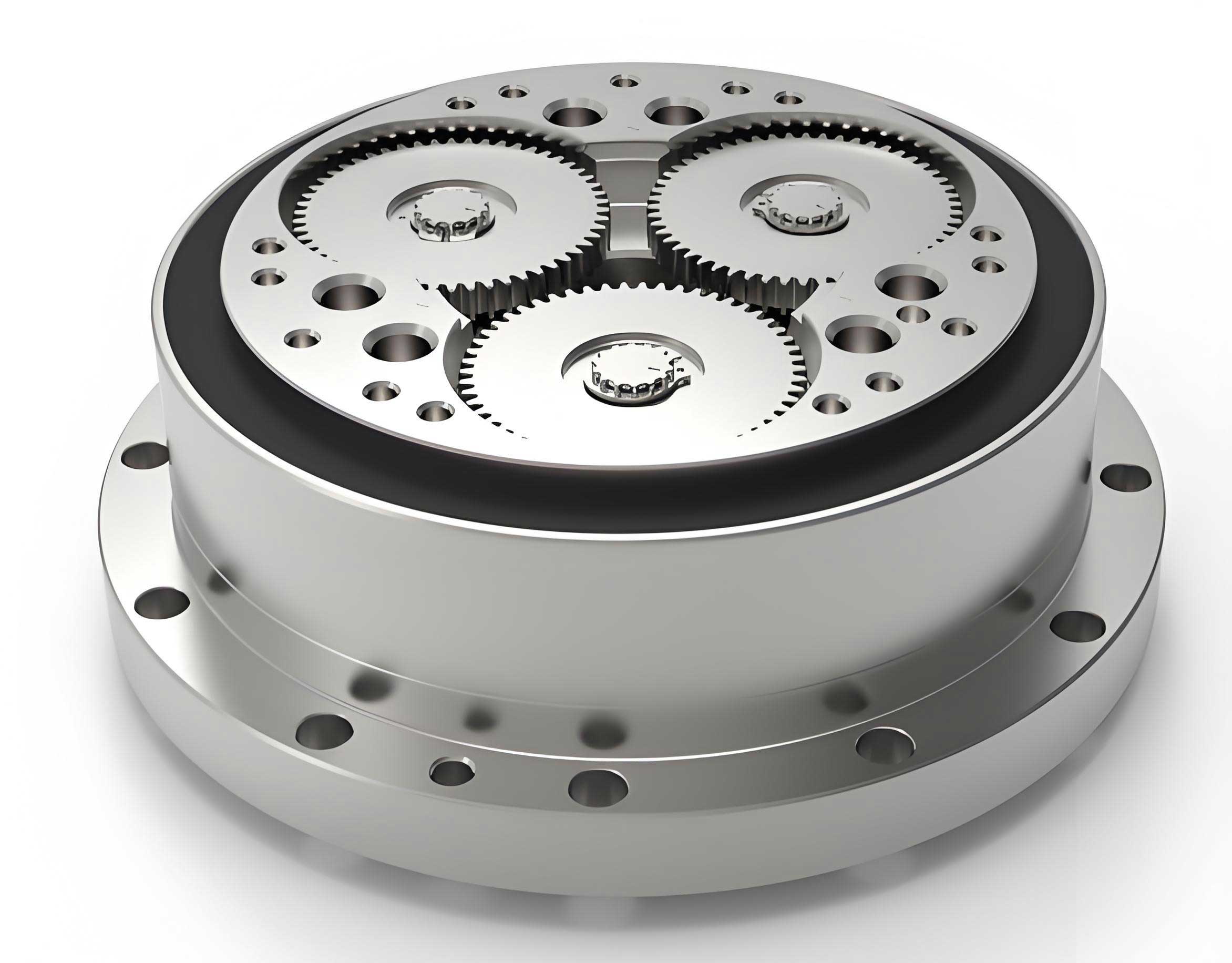
The rotary vector reducer achieves its high reduction ratio through a two-stage power transmission system. The operational principle can be understood by tracing the power flow. The input rotation from a servo motor is transmitted to the input shaft and then to a central sun gear. This engagement drives multiple planetary gears, accomplishing the first stage of speed reduction. Crucially, the rotation of these planetary gears serves as the input for the second stage. They are connected to crankshafts, which are fixed relative to the reducer’s housing. As the crankshafts rotate, they impart an eccentric motion (revolution) to the cycloid wheels. With the ring of needle rollers (the “pin gear”) held stationary, this eccentric motion forces the cycloid wheels to mesh with the needles. Due to the unique geometry of the cycloid profile, this revolution induces a reverse rotation (spin) of the cycloid wheels themselves. This spin is then transferred back to the crankshafts, causing them to orbit. Finally, this orbital motion is transmitted via bearings to the output carrier (planet架), which delivers the reduced output speed. This compact and robust kinematic chain is what defines the rotary vector reducer.
The overall transmission ratio, $i_{16}$, of the rotary vector reducer can be derived using the fixed carrier method and is expressed as:
$$ i_{16} = 1 + \frac{z_2}{z_1} z_5 $$
where $z_1$ is the number of teeth on the input sun gear, $z_2$ is the number of teeth on the planetary gear, and $z_5$ is the number of needle pins.
The widespread adoption of the rotary vector reducer in robotics stems from its distinct advantages over other减速器 types:
| Feature | Description |
|---|---|
| Structural Compactness | The transmission elements are positioned between the support bearings of the output carrier, leading to a very short axial length. |
| High Stiffness & Impact Resistance | The output carrier is inherently rigid and is supported in a simply-supported beam configuration, unlike the cantilevered output of many other reducers. |
| High Efficiency | The extensive use of rolling contacts (bearings and gear meshes) results in typical efficiencies ranging from 85% to 92%. |
| Smooth Operation & Long Life | The low-speed cycloid stage has multiple teeth in simultaneous contact, and the optimized bearing arrangements reduce relative rotational speeds, enhancing lifespan. |
| High Precision & Low Backlash | Precision manufacturing and the multi-tooth engagement of the cycloid stage yield high rotational accuracy and minimal lost motion. |
| Wide Ratio Range | By altering the gear counts in the first stage, a wide range of reduction ratios (commonly 31 to 171) can be achieved. |
Theoretical Load Analysis of the Cycloid Wheel
Accurately determining the load distribution on the cycloid wheel is a prerequisite for any meaningful strength evaluation. In an ideal, zero-backlash scenario, approximately half of the needle pins would be in contact with the cycloid wheel. However, practical manufacturing tolerances and necessary clearances significantly alter this load distribution. Empirical and analytical studies indicate that for a standard design, typically around 7 pairs of teeth are in load-bearing contact simultaneously under torque. This analysis will consider this realistic engagement condition.
To simplify the complex contact mechanics into a tractable model for stress analysis, the following assumptions are made:
- The material of the cycloid wheel is continuous, homogeneous, and isotropic.
- The friction forces at the tooth contact interfaces are negligible for the purpose of calculating bulk stresses.
- The contact load between the cycloid wheel and each needle pin acts along the common normal line at the point of contact.
The force diagram reveals a unique characteristic: the reaction forces from the engaged needle pins are not parallel. Their lines of action converge at a specific instantaneous center of rotation. The magnitude of the force on the i-th engaged tooth, $F_i$, can be calculated using the formula derived from the mechanics of the cycloid drive:
$$ F_i = \frac{4 T_c}{K_1 Z_c r_p} \cdot \frac{\sin \phi_i}{\left(1 + K_1^2 – 2K_1 \cos \phi_i \right)^{0.5}} $$
where:
- $T_c$ is the resisting torque on the cycloid wheel. For a standard two-cycloid-wheel design with typical manufacturing precision, $T_c \approx 0.55T$, where $T$ is the total output torque.
- $K_1$ is the shortening factor, defined as $K_1 = \frac{a Z_p}{r_p}$.
- $Z_c$ is the number of lobes on the cycloid wheel ($Z_c = Z_p – 1$).
- $r_p$ is the radius of the needle pin center circle.
- $\phi_i$ is the angular position of the i-th needle pin relative to the line of centers.
The parameters for a sample rotary vector reducer model, RV-20E, are listed below. The calculated forces for the seven engaged teeth (numbered 2 through 8 in the engagement zone) are also presented.
| Parameter | Symbol | Value |
|---|---|---|
| Pin Center Circle Radius | $r_p$ | 52.5 mm |
| Pin Radius | $r_{rp}$ | 2 mm |
| Number of Needle Pins | $Z_p$ | 40 |
| Eccentricity | $a$ | 1 mm |
| Shortening Factor | $K_1$ | 0.7619 |
| Crank Bearing Hole Diameter | $d_b$ | 26.5 mm |
| Center Distance between Bearing Holes | $s$ | 55 mm |
| Cycloid Wheel Thickness | $b_c$ | 9 mm |
| Tooth Number (i) | Angle $\phi_i$ (degrees) | Force $F_i$ (Newtons) |
|---|---|---|
| 2 | 13.5 | 1549.1 |
| 3 | 22.5 | 1920.8 |
| 4 | 31.5 | 2055.0 |
| 5 | 40.5 | 2085.8 |
| 6 | 49.5 | 2063.3 |
| 7 | 58.5 | 2008.1 |
| 8 | 67.5 | 1929.6 |
The direction of each force $F_i$ is along the line connecting the contact point to the instantaneous center, and its point of application is the theoretical contact point between the cycloid tooth and the needle pin. The crankshaft bearing holes apply reaction forces to the cycloid wheel. For the purpose of static stress analysis, these can be effectively modeled as fixed hinge constraints, which simplifies the load application in the FEA model without compromising the accuracy of the stress field within the cycloid wheel body.
Computational Modeling and Finite Element Analysis
Three-Dimensional Model Generation
The complex geometry of the cycloid tooth profile necessitates a parametric modeling approach. The standard parametric equations for a cycloid profile are given by:
$$ \begin{aligned}
x_c &= \left[ r_p – r_{rp} \Phi^{-1}(K_1, \phi) \right] \cos\left[(1-i_H)\phi\right] – \left[ a – K_1 r_{rp} \Phi^{-1}(K_1, \phi) \right] \cos(i_H \phi) \\
y_c &= \left[ r_p – r_{rp} \Phi^{-1}(K_1, \phi) \right] \sin\left[(1-i_H)\phi\right] – \left[ a – K_1 r_{rp} \Phi^{-1}(K_1, \phi) \right] \sin(i_H \phi)
\end{aligned} $$
where $\Phi^{-1}(K_1, \phi)$ is the generating factor and $i_H = Z_p / Z_c$ is the transmission ratio between the cycloid wheel and the pin ring. By substituting the parameters from Table 1 into these equations, the precise tooth profile curve for the RV-20E cycloid wheel is programmatically generated. This curve is then used as the basis for extruding the solid three-dimensional model of the cycloid wheel, including its central bearing holes and mounting features, resulting in an accurate digital twin ready for analysis.
Finite Element Analysis Setup and Execution
While general-purpose FEA software like ANSYS is powerful, the integrated Simulation module within SolidWorks offers distinct advantages for this specific application. The primary benefit is the ease of applying the complex, multi-point contact loads directly onto the intricate curved surfaces of the cycloid teeth, which can be cumbersome in other pre-processors.
The material assigned to the cycloid wheel is bearing steel GCr15, a common choice for such high-stress components due to its high hardness and fatigue resistance. The material properties defined in the simulation are:
| Property | Value |
|---|---|
| Young’s Modulus (Elasticity) | 208 GPa |
| Poisson’s Ratio | 0.3 |
| Density | 7.8 g/cm³ |
The simulation setup proceeds as follows:
- Constraints: The inner surfaces of the two crankshaft bearing holes are assigned fixed hinge (cylindrical) constraints. This correctly represents the kinematic support provided by the crankshaft bearings.
- Load Application: To apply the tooth forces $F_i$, the contact zones on the relevant cycloid teeth must be identified. This is done by geometrically partitioning the tooth surfaces to create distinct faces corresponding to the theoretical contact points. A normal force with the magnitude specified in Table 2 is then applied to each of these seven faces. The direction for each force is defined perpendicular to the tooth profile at that partition.
- Meshing: A standard solid mesh is generated for the component. The software automatically refines the mesh in areas of high geometric curvature and near the applied loads and constraints to ensure solution accuracy. A converged mesh with an appropriate element size is selected for the final analysis.
Analysis Results and Discussion
The finite element analysis solves the linear elastic boundary value problem and provides detailed results for deformation, strain, and stress. The post-processing reveals the following key insights into the behavior of the cycloid wheel within the rotary vector reducer under load.
Displacement Distribution: The nodal displacement plot shows that the maximum deformation occurs not on the tooth with the highest load, but on tooth #8, with a displacement magnitude of approximately 0.0271 mm. Tooth #2, subjected to the smallest load, exhibits the least displacement. The deformation pattern clearly shows the wheel flexing in response to the asymmetric loading from the seven contact points, with the area between the heavily loaded teeth and the constrained bearing holes experiencing the most significant bending.
Strain Distribution: The equivalent strain results correlate strongly with the applied load magnitude. The highest strain concentrations are observed in the root regions of teeth #4, #5, and #6, which are the teeth carrying the largest forces (as per Table 2). The maximum equivalent strain value is approximately 0.00193, located near tooth #6. This indicates the areas most prone to fatigue initiation under cyclic loading.
Stress Distribution: The von Mises stress criterion, suitable for ductile materials like GCr15 steel, is used to evaluate yield strength. The results are critically important. The maximum von Mises stress is found to be approximately 733 MPa, localized at the root fillet of tooth #6. This stress concentration is expected due to the combined effect of bending and direct compression from the tooth load. The stress field also shows elevated stress levels around the boundaries of the crankshaft bearing holes, resulting from the reaction forces.
The most significant finding is a comparison of this maximum operational stress with the material’s yield strength. High-quality GCr15, after proper heat treatment (quenching and tempering), typically has a yield strength ($\sigma_y$) well above 1200 MPa and an ultimate tensile strength even higher. Therefore, the calculated maximum stress of 733 MPa provides a substantial safety margin:
$$ \text{Factor of Safety} = \frac{\sigma_y}{\sigma_{max}} > \frac{1200 \text{ MPa}}{733 \text{ MPa}} \approx 1.64 $$
This confirms that the cycloid wheel design, under the specified operating conditions and for this model of rotary vector reducer, possesses adequate static strength. The risk of yielding or immediate fracture under peak load is minimal.
Conclusion
This comprehensive analysis successfully bridges theoretical mechanics and modern computational engineering to evaluate a critical component. The study began with a detailed load distribution analysis for a cycloid wheel within a rotary vector reducer, identifying seven teeth in simultaneous engagement and calculating their respective loads. A high-fidelity parametric model was then constructed based on the precise cycloidal geometry.
Subsequent finite element analysis using the static stress module provided a clear visualization of the component’s response. The results delineated the displacement field, strain concentrations, and, most importantly, the von Mises stress distribution. The analysis pinpointed the tooth root near the region of highest load as the location of peak stress. Crucially, the computed maximum stress of 733 MPa was found to be significantly lower than the expected yield strength of the bearing steel material (> 1200 MPa).
Therefore, it is conclusively verified that the cycloid wheel for the analyzed RV-20E type rotary vector reducer possesses sufficient mechanical strength to withstand the designated operational loads. The methodology and results presented herein provide a validated framework and essential design reference for ensuring the structural reliability and safe application of cycloid wheels in precision rotary vector reducers, contributing to the overall performance and longevity of advanced robotic systems.