
The evolution of product design and manufacturing has fundamentally shifted towards paradigms characterized by lifecycle orientation, concurrency, integration, and agility. Traditional, isolated design methodologies, reliant on centralized resources and regional economic models, are increasingly inadequate for this new landscape. There is a compelling need for a demand-driven, rapidly responsive product development model—networked design and manufacturing. Transforming traditional, standalone mechanical design processes into collaborative, network-enabled workflows is not merely an enhancement; it is an inevitable trend for the design of complex machinery components. This transition facilitates unprecedented resource sharing, enables multi-user collaborative design, and significantly amplifies design efficiency, paving the way for truly informational and automated design processes. In this context, I explore the implementation of such a networked system specifically for the design of screw gears, commonly referred to as worm gears, utilizing modern web and component technologies.
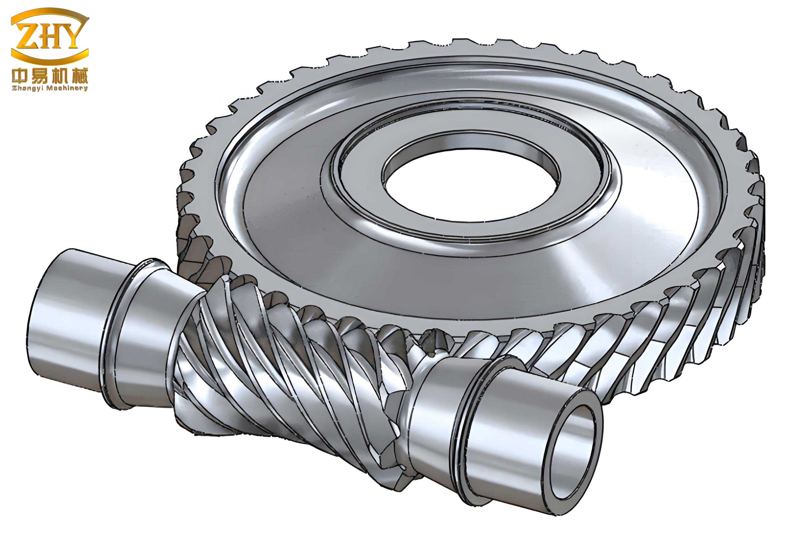
Screw gears represent a crucial power transmission element used to transfer motion and power between non-parallel, non-intersecting shafts, typically at a 90° angle. Their operational advantages are significant, including high reduction ratios, smooth and quiet operation, compact design, and the potential for self-locking. However, these benefits are counterbalanced by notable disadvantages, such as relatively low mechanical efficiency and the requirement for expensive, non-ferrous materials for the gear wheel to ensure proper wear characteristics. The design process for screw gears is inherently complex. It involves numerous iterative calculations, extensive consultation of standardized tables for parameters like gear tooth dimensions and materials, and referencing various diagrams for factors such as geometry and lubrication. This traditional manual approach is not only time-consuming and inefficient but also prone to human error, especially during the necessary strength verification and recalibration phases. While computer-aided design software has alleviated some of these burdens in standalone environments, the integration of screw gear design with network technology for collaborative, resource-shared design remains a largely underexplored domain. This work addresses that gap by proposing and implementing a web-based design system for screw gears, leveraging key technologies to enable efficient, parameterized design within a networked environment.
System Architecture and Operational Model for Resource Sharing
The foundation of any effective networked design system is a robust architecture that facilitates seamless resource sharing. In mechanical component design, resources encompass a vast array of information types: design standards, specifications for standard and common parts, technical drawings, 2D/3D digital models, material databases, manufacturing process data, and various technical documentation. These resources exist in diverse formats—text files, data files, graphics, or digital models—often stored across different departments or individual workstations. The geometric data itself may be locked in proprietary formats from various CAD systems. Effective sharing of these heterogeneous resources is paramount to improving design efficiency, shortening development cycles, and enhancing overall quality. To tackle this challenge, I propose a three-tier Browser/Server (B/S) architecture as the core framework for resource sharing.
This system is developed using a three-tier B/S application structure based on standard Internet/Intranet protocols. The operational model is clearly stratified:
- Presentation Tier (Client Layer): The user interacts with the system solely through a standard web browser. No specialized client software installation is required, ensuring universal accessibility and ease of maintenance.
- Application Logic Tier (Server Layer): This tier, typically a web server (e.g., Microsoft IIS, Apache), handles all business logic and application processing. It receives requests from the client browser, processes them, executes the necessary application programs or components, interacts with the database, and dynamically generates the results.
- Data Tier (Database Layer): This tier consists of a dedicated database server (e.g., Microsoft SQL Server, MySQL) that manages all persistent data—design parameters, calculation results, material properties, user information, and shared resource metadata.
In this model, a client submits a request via their browser to the web server. The web server processes this request, which may involve querying the database and executing specific application components. The results are then formatted into Hypertext Markup Language (HTML) pages and sent back to the client’s browser for display. This architecture centralizes application management and logic on the server, drastically simplifying client-side requirements and enabling true cross-platform collaboration. The separation of concerns also enhances security, scalability, and system maintenance.
A Model for Networked Design Resource Sharing
Building upon the three-tier architecture, a comprehensive model for a networked design resource sharing system can be conceptualized. This model envisions an integrated product development environment where all participants, potentially across different organizational units or even different companies, collaborate through a unified web-based interface.
Within an enterprise, an Intranet connects all internal departments, managing and organizing design and production activities on a local network. For broader collaboration, multiple enterprises can interconnect via the Internet, forming a larger virtual system. This interconnected network facilitates information resource sharing and integrates design and manufacturing processes across organizational boundaries. The system becomes a unified product research and development platform. In this platform, all design participants, using only a browser, can access and share design documents, calculation modules, standard parts libraries, and digital models. They collaboratively contribute to the development of a mechanical product, such as a complex assembly requiring precisely designed screw gears. The resources—be it a newly calculated set of screw gear parameters, a 3D model of a gear housing, or a material selection guide—are stored, versioned, and accessed centrally, breaking down information silos and accelerating the design cycle.
| Aspect | Traditional Standalone Design | Networked Resource-Sharing Design |
|---|---|---|
| Resource Access | Local files, limited manuals, isolated databases. | Centralized, version-controlled databases of materials, standards, and past projects. |
| Collaboration | Sequential; files exchanged via email or shared drives. | Real-time or asynchronous concurrent design; multiple experts can work on or review the same screw gear design. |
| Calculation Tools | Local executable files or scripts; updates are manual. | Server-side components (e.g., COM); always up-to-date, consistent version for all users. |
| Design Knowledge | Tribal knowledge, experience-dependent. | Captured in shared rules, automated checks, and component logic, ensuring design consistency. |
| Deployment & Maintenance | Installation required on every PC; updates are distributed manually. | Zero client installation; updates are made once on the server and instantly available to all. |
Core Technologies for Implementing a Screw Gear COM Component
The realization of a practical networked design system for screw gears hinges on the effective integration of several core web and software technologies. Primarily, this involves Active Server Pages (ASP) for dynamic web content generation, the Component Object Model (COM) for encapsulating complex design logic, and networked database technology for persistent, shared data storage.
Active Server Pages (ASP) and Component Object Model (COM)
ASP is a server-side scripting environment developed by Microsoft. It is not a language itself but a framework that allows you to combine HTML, client-side and server-side scripts (like VBScript or JScript), and COM components to create powerful, dynamic, and interactive web applications. The operational principle is straightforward: when a user requests an ASP page, the web server processes any server-side scripts contained within the page. These scripts can perform calculations, access databases, and crucially, instantiate and interact with COM components. The server then sends the resulting pure HTML output to the client’s browser.
COM is a binary standard for creating reusable software components. A COM component is a piece of compiled, executable code (as a Dynamic Link Library – DLL or an executable – EXE) that exposes its functionality through well-defined interfaces. The synergy between ASP and COM is where the true power for engineering applications lies. ASP provides the web interaction layer, while COM components provide the robust, compiled business logic. For screw gear design, all the complex algorithms for geometry calculation, stress analysis, strength verification (based on standards like AGMA or ISO), and efficiency estimation are implemented within a dedicated COM component. The ASP page simply acts as a facilitator, collecting input parameters from the user, passing them to the screw gear component, and formatting the results for display.
The advantages of using COM components in this context are substantial:
- Language Independence: COM components can be developed in various programming languages such as Visual Basic, C++, or C#. For the computational heavy-lifting required in screw gear design, a language like Visual Basic offers rapid development and ease of debugging, while compiled C++ offers maximum performance. The binary nature ensures compatibility across Windows platforms.
- Reusability and Encapsulation: A well-designed screw gear COM component exposes interfaces for key operations like `CalculateGeometry`, `CheckStrength`, or `GenerateModel`. This black-box model allows the complex logic to be reused in different contexts—within the web application, a standalone desktop tool, or even another server process—without exposing the source code.
- Performance and Manageability: Compiled COM components execute significantly faster than interpreted ASP scripts. Centralizing the design logic in a server-side component also simplifies management, version control, and security, as the core intellectual property (the design algorithms) resides securely on the server.
Network Database Technology
The integration of web technology with database technology is fundamental. A networked database provides a centralized, reliable, and scalable repository for all system data. In our screw gear design system, the database stores several critical data sets:
- User Input Parameters: Initial design requirements (power, speed, ratio, center distance constraints).
- Standard Reference Data: Material property tables (yield strength, hardness), tooth form coefficients, allowable stress diagrams, lubrication parameters.
- Calculation Results: Final geometric parameters of the screw gears, safety factors, efficiency predictions, and warnings.
- User and Session Data: Design histories, user preferences, and project metadata.
Using standardized protocols like ODBC or OLE DB, the ASP scripts and COM components on the web server can query and update this database. This three-tier separation (client browser, web/application server, database server) enhances system performance, security (direct database access from the client is prevented), and flexibility, allowing the database and application logic to be scaled independently.
System Implementation: A Case Study in Screw Gear Design
Based on the models and technologies described, I have developed a functional prototype of a parameterized screw gear design system operating on an Internet/Intranet framework. This system exemplifies the transition from concept to practical application.
The digital modeling of the screw gears is achieved using SolidWorks, a mainstream CAD system. A key feature of this integration is the ability to output the generated 3D models in neutral, standardized formats such as STEP, IGES, or SAT, ensuring compatibility with other CAD systems used by collaborators. Similarly, 2D engineering drawings can be exported as DXF or DWG files for use in AutoCAD or other drafting software, completing the digital thread from calculation to manufacturing documentation.
The user experience is streamlined through a web interface. A remote user accesses the system via a browser, logs in after authentication, and arrives at the homepage. Upon selecting the screw gear design module, they are presented with an input form. This form captures all necessary initial parameters required to define the screw gear set. Key input parameters typically include:
- Input power ($P$ in kW) and rotational speed ($n_1$ in rpm) of the worm.
- Desired gear ratio ($i$) or number of threads/starts on the worm ($z_1$).
- Center distance constraints ($a$ in mm).
- Material selections for the worm (e.g., hardened steel) and the gear (e.g., bronze alloy).
- Application factors (load type, duty cycle).
Upon submission, these parameters are immediately stored in a designated table within the SQL Server database. The ASP page then instantiates the screw gear COM component, passing the input parameters to it. The component executes its encapsulated logic, which involves the following key computational steps:
- Preliminary Geometry Sizing: Based on center distance and ratio, initial estimates for the worm pitch diameter ($d_1$), gear face width ($b_2$), and module ($m$) are made, often referencing standard series.
$$ m \approx \frac{2a}{q + z_2} $$
where $q$ is the diameter factor and $z_2$ is the number of teeth on the gear. - Detailed Geometry Calculation: Exact dimensions for lead ($p_z$), lead angle ($\gamma$), throat diameter, root diameters, etc., are calculated.
$$ \gamma = \arctan\left(\frac{z_1 \cdot m}{d_1}\right) $$
$$ p_z = \pi \cdot m \cdot z_1 $$ - Strength and Wear Verification: The component performs both bending stress and contact (wear) stress checks according to relevant standards. This is often an iterative process where geometries are adjusted if safety factors ($S_F$, $S_H$) are inadequate.
$$ \sigma_F = \frac{K_A \cdot K_v \cdot F_t}{b_2 \cdot m \cdot Y} \leq \sigma_{FP} $$
$$ \sigma_H = Z_E \cdot \sqrt{\frac{K_A \cdot K_v \cdot F_t}{d_1 \cdot b_2} \cdot \frac{Z_R}{Z_I}} \leq \sigma_{HP} $$
Here, $K_A$ is the application factor, $K_v$ is the dynamic factor, $F_t$ is the tangential load, $Y$ is the geometry factor for bending, $Z_E$ is the elastic coefficient, $Z_R$ is the roughness factor, and $Z_I$ is the geometry factor for contact stress. $\sigma_{FP}$ and $\sigma_{HP}$ are the allowable stresses. - Efficiency Calculation: The system estimates the efficiency ($\eta$) based on the lead angle and coefficient of friction ($\mu$).
$$ \eta \approx \frac{\tan \gamma}{\tan(\gamma + \phi’)} $$
where $\phi’ = \arctan(\mu)$ is the friction angle. - Thermal Check: A simple thermal rating may be performed to ensure adequate heat dissipation.
All final results—the complete set of screw gear geometric parameters, calculated safety factors, efficiency, and any warning messages—are written back to the database. The ASP page then retrieves these results and presents them to the user in a clear, formatted output page. Furthermore, the system can trigger the generation of a 3D model and a 2D engineering drawing based on the final parameters, the links to which are provided on the results page. The user has immediate access to a complete, verified screw gear design package.
| Parameter Category | Symbol | Value | Unit |
|---|---|---|---|
| Input Parameters | |||
| Input Power | $P$ | 5.5 | kW |
| Worm Speed | $n_1$ | 1450 | rpm |
| Gear Ratio | $i$ | 20 | – |
| Center Distance | $a$ | 125 | mm |
| Calculated Geometry | |||
| Axial Module | $m$ | 5.0 | mm |
| Number of Worm Threads | $z_1$ | 2 | – |
| Number of Gear Teeth | $z_2$ | 40 | – |
| Worm Pitch Diameter | $d_1$ | 50.0 | mm |
| Gear Pitch Diameter | $d_2$ | 200.0 | mm |
| Lead Angle | $\gamma$ | 11.31 | ° |
| Performance Results | |||
| Bending Safety Factor | $S_F$ | 2.1 | – |
| Contact Safety Factor | $S_H$ | 1.8 | – |
| Estimated Efficiency | $\eta$ | 85 | % |
Extended Applications and Future Development Directions
The implementation described for screw gears is a template that can be generalized to a vast array of mechanical components. The core paradigm—web-based interface, server-side component logic, and a central database—is universally applicable. Imagine a comprehensive portal where engineers can design not only screw gears but also parallel shaft gears, bearings, shafts, springs, and couplings, all with the same collaborative, resource-shared philosophy. The COM component architecture allows for a library of design components, each encapsulating the expertise for a specific part type. Future extensions of this work are multifaceted:
- Integration with Cloud Services and AI: The system can be migrated to a cloud infrastructure, providing on-demand scalability and global accessibility. Furthermore, machine learning algorithms could be integrated to suggest optimal initial parameters for screw gears based on historical successful designs, predict potential failure modes, or optimize for objectives like minimum weight or maximum efficiency.
- Advanced Collaboration Features: Implementing real-time collaborative editing of design notes, integrated discussion forums for specific projects, and workflow management tools would enhance the collaborative aspect beyond simple resource sharing.
- Full Lifecycle Integration: The system can be expanded to link the screw gear design data directly with downstream processes: generating CNC code for manufacturing the gears, creating bill of materials (BOM), and linking with enterprise resource planning (ERP) systems for procurement of the specified bronze or steel.
- Standardization and Interoperability: Future versions could leverage more modern, platform-independent component models like .NET assemblies or web services (SOAP/REST APIs) instead of or in addition to COM, improving cross-platform compatibility. Using XML schemas to define the data exchange format for screw gear parameters can ensure seamless interoperability with other engineering software systems.
Conclusion
I have presented a method for the networked design of screw gears utilizing ASP technology, COM component technology, and networked database technology. The developed prototype application validates the effectiveness and correctness of this approach. It demonstrates how traditional, calculation-intensive mechanical design tasks can be transformed into streamlined, collaborative, web-based processes. The system simplifies the screw gear design workflow by automating table look-ups, iterative calculations, strength verification, and design documentation generation, thereby yielding substantial gains in designer productivity and consistency. This work serves as a practical case study in merging traditional engineering design with modern network technology. More broadly, the COM component-based methodology establishes a viable implementation model and points a clear direction for the informatization and network-enablement of mechanical product design. The move towards such resource-sharing, collaborative systems is not merely a technological upgrade but a fundamental shift in how we approach the creation of complex mechanical systems, with screw gears being one foundational element in this new, connected engineering landscape.