
In the field of mechanical engineering, gear cutting for spiral bevel gears is a critical process that ensures efficient power transmission in various applications, such as automotive differentials and industrial machinery. The precision of gear cutting directly impacts the performance, noise, and durability of gear systems. Traditional methods, like the Gleason approach, have been widely used for gear cutting adjustments, but they often involve inherent errors due to the fixed selection of reference points on the gear tooth surface. This can lead to mismatches between the calculated contact pattern center and the actual gear meshing zone, necessitating time-consuming manual adjustments during gear cutting. To address this, we propose a novel method—referred to as the ZHY method—that allows for arbitrary point selection on the gear surface as a reference, thereby eliminating theoretical errors and enhancing gear cutting efficiency and quality. This article delves into the mathematical foundation, computational steps, and practical implications of this new gear cutting adjustment method, aiming to provide a comprehensive guide for engineers and researchers involved in advanced gear manufacturing.
The core innovation of our gear cutting method lies in its flexibility in choosing reference points. In conventional gear cutting processes, such as the Gleason full formate method with cutter tilt, the reference point for generating the pinion is fixed at the midpoint of the tooth space on the gear’s pitch cone. This point, denoted as P, may be distant from the actual contact pattern center C, leading to discrepancies that require empirical adjustments post-gear cutting. Our ZHY method overcomes this by enabling the selection of any point on the gear tooth surface as the reference, ensuring that the contact pattern center aligns precisely with the calculated point. This not only streamlines the gear cutting process but also improves the meshing performance of the gears. Throughout this discussion, we will emphasize the term “gear cutting” to highlight its centrality in our methodology, as precise gear cutting is essential for achieving optimal gear functionality.
To begin, let’s outline the gear cutting process for the gear member (referred to as gear 2) using the dual-face generating method with cutter tilt. This method involves using a cutter head that can be tilted to compensate for pressure angle errors, which is crucial in gear cutting for spiral bevel gears. The theoretical blade spacing, denoted as W, is calculated based on the gear geometry and cutter parameters. For gear cutting, we select a cutter with a specific blade angle, and the pressure angle at the gear root cone is adjusted to ensure proper tooth form. The formula for the theoretical blade spacing is given by:
$$W = \frac{s_p}{\cos \alpha_t} + 2h_{fp} \tan \alpha_t$$
where \(s_p\) is the chordal tooth thickness at the pitch circle, \(\alpha_t\) is the tool blade angle, and \(h_{fp}\) is the dedendum height. In practical gear cutting, a standard blade spacing value close to the theoretical one is chosen. The machine settings for gear cutting include parameters like the cradle angle, radial distance, and tilt angle, which are derived from geometric relationships on the gear’s pitch cone. For instance, the spiral angle at the midpoint of the tooth face width is critical in determining the machine setup. Below is a table summarizing the key machine adjustment parameters for gear cutting of gear 2 using the dual-face generating method with cutter tilt, based on a sample gear pair. All linear values are in millimeters, and angular values are in degrees, assuming a machine constant \(K_m = 1.5\) for illustration.
| Parameter | Symbol | Calculation Formula | Example Value |
|---|---|---|---|
| Cradle Angle | \(\theta_c\) | \(\theta_c = \beta_m + \Delta \alpha\) | 25.5° |
| Radial Distance | R_d | \(R_d = R_p \sin \Gamma\) | 150.2 mm |
| Tilt Angle | \(\tau\) | \(\tau = \arctan(\frac{\Delta \alpha}{\cos \beta_m})\) | 3.2° |
| Machine Ratio | M_r | \(M_r = \frac{N_g}{N_c}\) | 2.5 |
| Blade Spacing | W | As per formula above | 12.8 mm |
This table illustrates the essential parameters in gear cutting adjustments, emphasizing how each contributes to the precision of the gear cutting process. The formulas are derived from the geometric configuration of the gear and cutter during gear cutting, ensuring that the tooth surface is generated accurately.
Next, we delve into the concept of equidistant conjugate surfaces, which is fundamental to our gear cutting method. During gear cutting, the cutter surface and the gear tooth surface are related through an equidistant surface that accounts for the separation between them at the reference point. For gear 2, the distance from the cutter surface to its equidistant conjugate surface at point P is given by:
$$d = \frac{W}{2} \pm h_f$$
where the plus sign applies to the convex side and the minus sign to the concave side of the gear tooth. In gear cutting, this distance allows us to shift the reference point from P to any desired point C on the gear surface, corresponding to the center of the contact pattern. The coordinates of point C in the radial and axial directions, denoted as \(r_c\) and \(z_c\), are determined by:
$$r_c = r_p + \Delta r \cos \Gamma$$
$$z_c = z_p + \Delta r \sin \Gamma$$
where \(\Delta r\) is the shift along the gear’s pitch cone generatrix, and \(\Gamma\) is the pitch cone angle. This shift is crucial in gear cutting as it enables the alignment of the calculation reference with the actual contact zone. To model this mathematically, we use vector functions in a coordinate system attached to the gear and cutter. Let \(\mathbf{r}_c\) be the position vector of point C in the cutter coordinate system. The unit normal vector at point C on the equidistant surface is derived from the cutter geometry, and the meshing condition during gear cutting ensures that the common normal intersects the relative rotation axis. This leads to a set of nonlinear equations that can be solved using numerical methods like Newton’s method to determine the exact position of point C. The equations are:
$$\mathbf{n} \cdot (\mathbf{r}_c \times \mathbf{\omega}) = 0$$
$$\mathbf{r}_c = \mathbf{r}_p + \Delta \mathbf{r}$$
where \(\mathbf{n}\) is the unit normal vector, \(\mathbf{\omega}\) is the relative angular velocity vector, and \(\Delta \mathbf{r}\) is the displacement vector. Solving these equations iteratively during gear cutting computation ensures that the reference point is accurately placed for optimal contact pattern control.
Now, let’s consider the geometry of imaginary gears and the curvature relationships on equidistant conjugate surfaces. In gear cutting, we introduce imaginary gears that share the same tooth surface as the actual gear but have different pitch cone parameters. These imaginary gears, denoted as gear 1′ and gear 2′, facilitate the calculation of curvature corrections needed for precise gear cutting. The pitch cone angles and radii for these imaginary gears are calculated as follows:
$$\Gamma’ = \Gamma + \Delta \Gamma$$
$$R’ = R_p \frac{\sin \Gamma’}{\sin \Gamma}$$
where \(\Delta \Gamma\) is a small adjustment angle. The spiral angle at point C on the imaginary gear is derived from the gear cutting geometry and is given by:
$$\beta’ = \arctan\left( \frac{r_c \sin \beta_m}{R’} \right)$$
This angle influences the machine settings during gear cutting, particularly the tilt and cradle angles. The curvature of the equidistant surfaces at point C is analyzed to ensure second-order contact between the generated tooth surface and the desired surface. The principal curvatures and geodesic torsion are computed using differential geometry formulas. For instance, the normal curvature along the tooth trace direction, \(\kappa_n^t\), and along the profile direction, \(\kappa_n^p\), are given by:
$$\kappa_n^t = \frac{\cos^2 \phi}{\rho_t} + \frac{\sin^2 \phi}{\rho_p}$$
$$\kappa_n^p = \frac{\sin^2 \phi}{\rho_t} + \frac{\cos^2 \phi}{\rho_p}$$
where \(\phi\) is the angle between the tooth trace and the first principal direction, and \(\rho_t\) and \(\rho_p\) are the principal radii of curvature. In gear cutting, these curvatures are matched between the cutter and gear surfaces to minimize deviations. A curvature correction term \(\Delta \kappa\) is introduced to account for any discrepancies, ensuring that the gear cutting process yields a tooth surface that closely approximates the theoretical design. The correction is applied as:
$$\kappa_{adjusted} = \kappa_n^p \pm \Delta \kappa$$
where the sign depends on whether the convex or concave side is being cut. This step is vital in gear cutting for achieving the desired contact pattern and stress distribution.
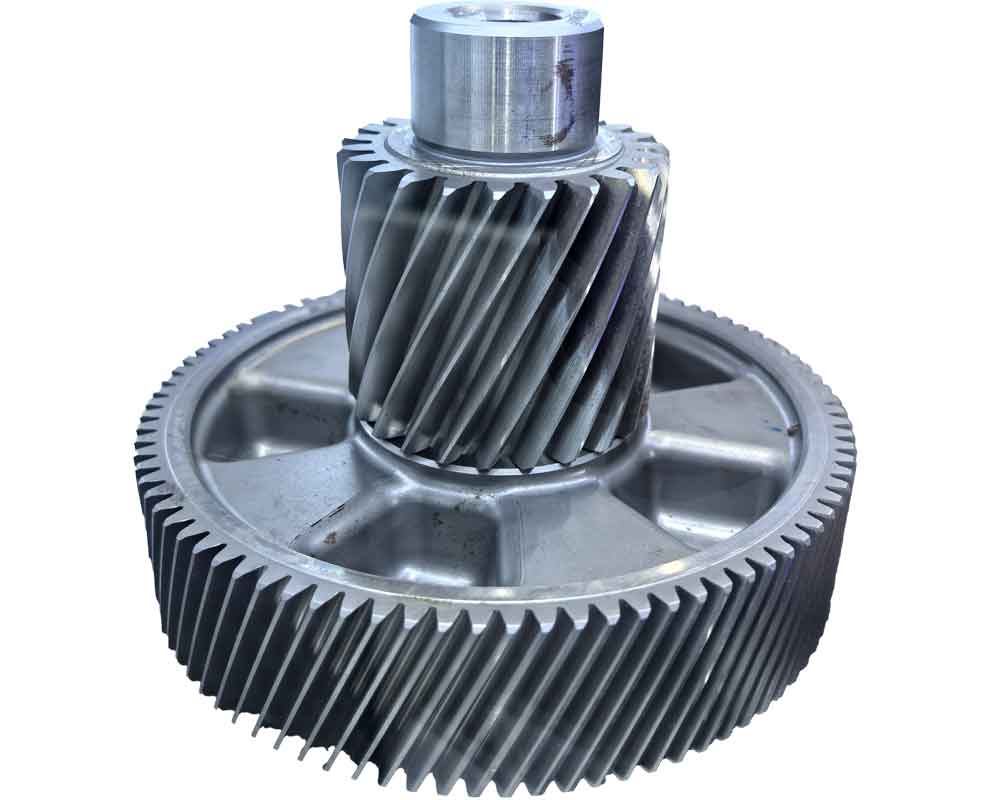
The image above illustrates a typical setup in gear cutting for spiral bevel gears, highlighting the complex interplay between the cutter, gear blank, and machine adjustments. Such visual aids are essential for understanding the practical aspects of gear cutting, especially when implementing advanced methods like the ZHY approach.
Moving on to the gear cutting adjustments for the pinion (gear 1), our method involves similar principles but with specific formulas tailored to the pinion generation. The machine settings for pinion gear cutting include the cutting installation angle, vertical offset, machine ratio, and cutter tilt parameters. These are derived from the geometry of the imaginary gears and the curvature corrections. For example, the cutting installation angle \(\delta_c\) is calculated as:
$$\delta_c = \arctan\left( \frac{\sin \Gamma’}{\cos \Gamma’ + M_r} \right)$$
where \(M_r\) is the machine ratio. The vertical offset \(V_o\) during gear cutting is given by:
$$V_o = R’ \sin \beta’ – K_m \cos \beta’$$
with \(K_m\) being the machine constant. The machine ratio for pinion gear cutting is adjusted based on the imaginary gear’s tooth count to ensure proper roll motion. The theoretical pressure angle deviation \(\Delta \alpha\) between the cutter blade angle and the desired pressure angle is compensated by tilting the cutter head, a common practice in gear cutting to achieve accurate tooth profiles. The formulas for these adjustments are summarized in the table below, which provides example values for two different sets of shift parameters \(\Delta r\) and \(\Delta \Gamma\). These parameters influence the final gear cutting settings and the resulting contact pattern.
| Parameter | Symbol | Formula for Pinion Gear Cutting | Example Set 1 | Example Set 2 |
|---|---|---|---|---|
| Installation Angle | \(\delta_c\) | \(\delta_c = \arctan(\frac{\sin \Gamma’}{\cos \Gamma’ + M_r})\) | 20.3° | 21.5° |
| Vertical Offset | \(V_o\) | \(V_o = R’ \sin \beta’ – K_m \cos \beta’\) | 15.2 mm | 14.8 mm |
| Machine Ratio | \(M_{r,p}\) | \(M_{r,p} = \frac{N_{1′}}{N_c}\) | 1.8 | 1.9 |
| Cutter Tilt Angle | \(\tau_p\) | \(\tau_p = \arcsin(\frac{\Delta \alpha}{\cos \beta’})\) | 2.5° | 2.8° |
| Radial Tool Position | \(R_{t,p}\) | \(R_{t,p} = \sqrt{R’^2 + V_o^2}\) | 152.7 mm | 151.3 mm |
This table underscores the variability in gear cutting parameters based on the chosen reference point, demonstrating the flexibility of our ZHY method. By adjusting \(\Delta r\) and \(\Delta \Gamma\), engineers can optimize the gear cutting process for different contact pattern requirements, reducing the need for post-cutting adjustments and enhancing overall gear quality.
The advantages of this new gear cutting method are manifold. Firstly, it eliminates the theoretical error inherent in traditional methods by allowing arbitrary reference point selection. This leads to a direct alignment between the calculated contact pattern center and the actual gear meshing zone, saving significant time in machine adjustment during gear cutting. Secondly, the method incorporates advanced curvature analysis and corrections, ensuring that the generated tooth surfaces have optimal contact characteristics for noise reduction and load distribution. Thirdly, by using imaginary gears and equidistant surfaces, the method provides a robust mathematical framework that can be adapted to various gear geometries and cutting conditions. In practical gear cutting applications, this translates to higher precision gears with improved performance and longevity.
To further illustrate the impact, consider the gear cutting process for a spiral bevel gear pair used in automotive differentials. Using the Gleason method, the gear cutting adjustments might result in a contact pattern shifted towards the toe or heel of the tooth, requiring manual correction that can take hours. With our ZHY method, the gear cutting parameters are computed based on a point near the desired contact center, yielding a pattern that meets specifications immediately after cutting. This not only speeds up production but also reduces scrap rates and enhances consistency in gear manufacturing. Moreover, the method’s reliance on numerical solutions ensures accuracy even for complex gear designs, making it suitable for high-performance applications like aerospace and renewable energy systems where gear cutting precision is paramount.
In conclusion, the ZHY method for gear cutting adjustment in spiral bevel gears represents a significant advancement over traditional approaches. By enabling flexible reference point selection and integrating detailed curvature corrections, it addresses the core limitations of existing gear cutting techniques. The mathematical derivations and computational steps outlined here provide a solid foundation for implementing this method in industrial settings. As gear cutting technology evolves, such innovations will play a crucial role in meeting the growing demands for efficiency, accuracy, and reliability in gear systems. We encourage further research and adoption of this method to push the boundaries of gear manufacturing excellence.
The formulas and tables presented are integral to the gear cutting process, and their correct application ensures successful gear production. For instance, the key equation for the shift in reference point is recapped below to emphasize its importance in gear cutting:
$$\Delta \mathbf{r} = (\Delta r \cos \Gamma, \Delta r \sin \Gamma, 0)$$
This vector displacement allows for precise control over the contact pattern during gear cutting. Additionally, the curvature matching condition is reiterated as:
$$\kappa_{gear} = \kappa_{cutter} \pm \Delta \kappa$$
where \(\Delta \kappa\) is the correction term derived from the imaginary gear analysis. By adhering to these principles, engineers can achieve superior results in gear cutting, making the ZHY method a valuable tool in modern gear design and manufacturing.
Overall, the integration of advanced mathematics with practical gear cutting adjustments underscores the interdisciplinary nature of gear engineering. As we continue to refine these methods, the focus remains on enhancing the gear cutting process to produce gears that meet the highest standards of performance and durability. The ZHY method is a step forward in this direction, offering a systematic approach that reduces reliance on empirical tweaks and elevates the science of gear cutting to new heights.