
In the field of gear manufacturing, the gear shaping process is a fundamental method for producing straight-toothed gears and racks. However, when it comes to machining long racks exceeding the worktable length limitations of standard gear shaping machines, significant challenges arise. Traditionally, long racks were segmented into shorter sections, each machined separately and then assembled using bolts and定位销孔. This approach not only increases computational and绘图 efforts but also complicates material preparation, marking, machining, and assembly. Moreover, segmented machining leads to reduced efficiency and difficulties in ensuring pitch accuracy and cumulative pitch error. In my experience, I have developed a novel positioning device that enables continuous gear shaping of long racks on standard machines, eliminating the need for segmentation and enhancing precision. This article delves into the principles of gear shaping, the design and application of this positioning device, and its mathematical underpinnings, with extensive use of tables and formulas to summarize key aspects.
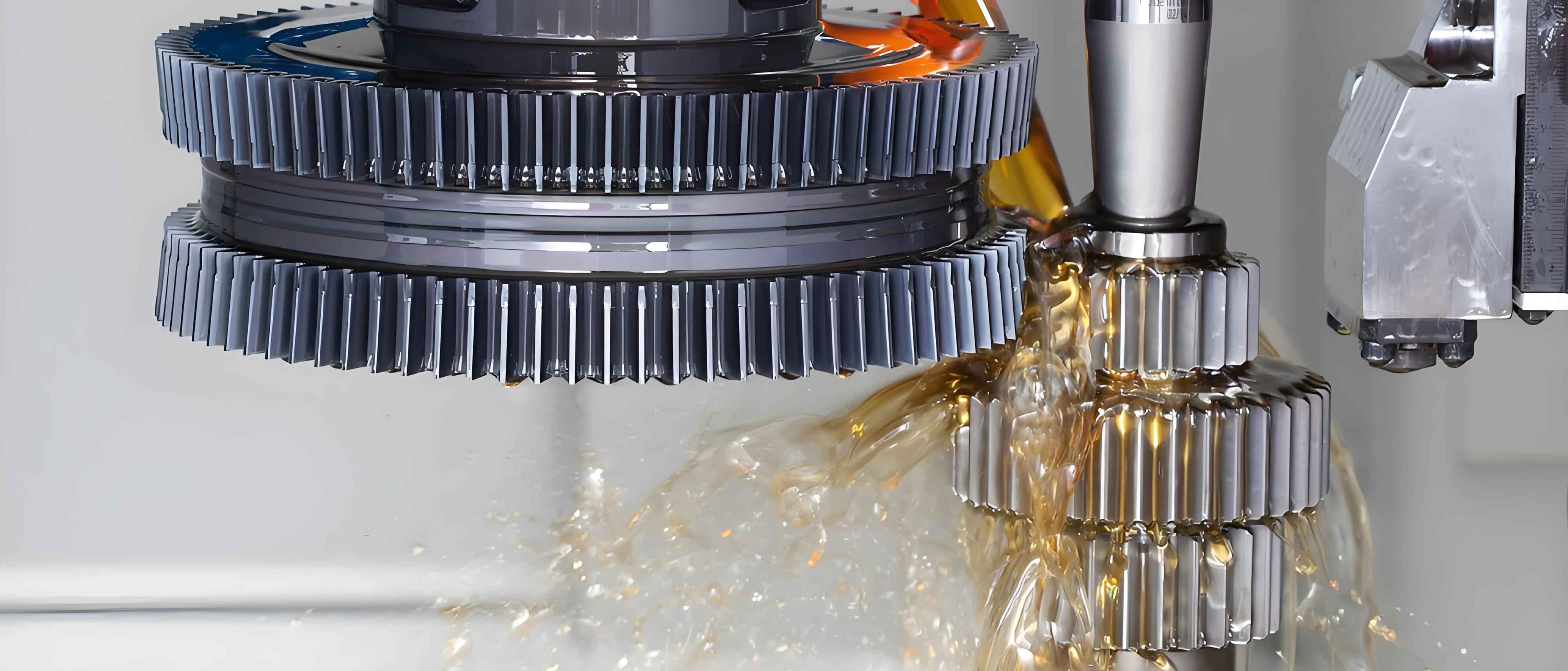
The gear shaping process employs a disc-shaped cutter that mimics a gear with relieved cutting edges. During operation, the cutter reciprocates axially while engaging with the workpiece in a synchronized rotational motion, gradually generating the tooth profile through an enveloping action. The fundamental relationship in gear shaping can be described by the kinematics of the tool-workpiece interaction. For a rack, the linear motion of the worktable corresponds to the pitch line movement. The tooth profile is formed as the cutter’s cutting edges trace out an involute or other specified curve. Mathematically, the generation of a rack tooth profile via gear shaping can be modeled using parametric equations. Let the cutter profile be defined by a function $C(\theta)$, where $\theta$ is the rotational parameter, and the workpiece motion is linear with displacement $s$. The generated profile $P(x,y)$ is the envelope of the family of curves defined by the cutter positions over time. This can be expressed as:
$$ P(x,y) = \bigcup_{t} \left[ T(t) \cdot C(\theta(t)) \right] $$
where $T(t)$ represents the transformation matrix accounting for both linear and rotational motions. For a standard rack, the pitch $p$ is constant, and the tooth spacing must adhere to strict tolerances. The cumulative pitch error over length $L$ is critical and is defined as:
$$ \Delta P_{\text{cum}} = \sum_{i=1}^{n} \Delta p_i $$
where $\Delta p_i$ is the individual pitch deviation for tooth $i$, and $n$ is the total number of teeth over $L$. In segmented machining, this error can accumulate disproportionately at joints, whereas continuous machining with proper positioning control minimizes it.
Traditional methods for long rack machining involve dividing the rack into segments of length less than the worktable capacity (e.g., 2000 mm). Each segment requires separate setup, including calculation of分段 points, addition of bolt holes, and alignment during assembly. This process is tedious and error-prone. The table below summarizes the drawbacks of traditional segmented machining compared to the proposed continuous method using the positioning device.
| Aspect | Traditional Segmented Machining | Continuous Machining with Positioning Device |
|---|---|---|
| Pre-machining Planning | Extensive calculations and drawings needed | Minimal; only standard setup required |
| Material Preparation | Multiple segments to be cut and handled | Single long blank used |
| Machining Time | High due to repeated setups | Reduced as setup is largely maintained |
| Pitch Accuracy | Relies on measurement and alignment at joints | Inherently better due to continuous process |
| Assembly Complexity | High; requires bolting and alignment | None; rack is monolithic |
| Cost | Higher due to extra operations and materials | Lower due to efficiency and reduced waste |
To overcome these limitations, I designed a positioning device that allows for sequential machining of long racks without losing tooth alignment. The device essentially fixes the relative position of the rack teeth to the worktable during shifts, ensuring pitch continuity. The core concept hinges on using a reference tooth block that engages with already machined teeth to reposition the workpiece accurately for the next section. This method leverages the precision of the gear shaping machine’s existing axes while introducing minimal additional error.
The positioning device consists of several key components, as illustrated in the figure above. It integrates with the standard worktable of a gear shaping machine, such as the Y51150 model mentioned in initial contexts. The main parts include a定位座 (positioning seat), a对齿块 (tooth engagement block), a夹具体 (clamping fixture), and associated fasteners. The table below lists these components and their functions in detail.
| Component | Function | Design Specifications |
|---|---|---|
| Positioning Seat (定位座) | Holds the tooth engagement block and provides a mounting base on the worktable | Thickness greater than minimum undercut width; machined flat and parallel |
| Tooth Engagement Block (对齿块) | Engages with machined teeth to establish positional reference | Precision ground teeth matching rack profile; fits into seat with tight tolerance |
| Clamping Fixture (夹具体) | Holds the rack blank against reference surfaces | Features vertical and horizontal datum planes (A and B) over full length; aligned within 0.02 mm |
| Clamping Bolts and压板 | Secures the rack blank during machining | Use of full-length压板 recommended for uniform pressure |
| T-slot Blocks | Anchors the device to the worktable T-slots | Standard T-bolts and nuts for rigidity |
The design ensures that the rack blank is always referenced to the same datum planes A and B, which are machined to high flatness and perpendicularity. The tooth engagement block is critical for transferring the tooth position from one machined section to the next. Its fit with the positioning seat is precision-controlled to minimize error propagation. Specifically, the block and seat have a sliding fit with dimensions 80H6 and 80h5, respectively. This clearance directly affects pitch error, as any play $\delta$ between them will translate into a linear displacement error $\Delta p$ during repositioning. The relationship can be approximated as:
$$ \Delta p \approx \delta $$
Given that the tolerance for a grade 7 rack specifies a pitch deviation limit of $\pm 0.02$ mm, and the H6/h5 fit typically yields clearances below 0.01 mm, this design comfortably meets the requirement. Moreover, the cumulative error over multiple shifts is not additive because each repositioning uses the same reference surfaces, thus maintaining consistency.
The implementation of this device in a gear shaping operation follows a systematic procedure. I will outline the steps in detail, incorporating formulas where relevant to quantify adjustments.
Step 1: Initial Setup and First Section Machining
The clamping fixture is mounted on the worktable and aligned so that its datum planes A and B are parallel to the machine axes within 0.02 mm over the full 2000 mm length. This is verified using dial indicators. The rack blank, pre-machined for parallelism and perpendicularity, is placed against A and B and clamped securely. The gear shaping process then begins, machining the first section (e.g., 1500–2000 mm length). The cutter is fed radially into the workpiece in increments to achieve full tooth depth. The radial infeed $d_r$ per stroke is controlled to avoid tool overload; typically, for module $m$ teeth, the total depth $h = 2.25m$ is reached in 3–4 passes. The relationship between infeed and number of passes $n_p$ is:
$$ d_r = \frac{h}{n_p} $$
During this phase, the pitch is generated based on the machine’s lead screw or CNC control, ensuring consistency within the first section.
Step 2: Establishing Reference and Zeroing
Once the first section is machined to final dimensions, the tooth thickness is measured and adjusted to the drawing specification. The cutter head feed dial is zeroed, and a dial indicator is set on the headstock to record the exact endpoint position. This step ensures that subsequent sections are cut to the same depth. Let $D_0$ be the dial indicator reading at the endpoint. A physical stop may also be set for safety. The cutter is then retracted, disengaging from the workpiece.
Step 3: Installing and Engaging the Tooth Block
The tooth engagement block is inserted into the positioning seat and moved into full mesh with the machined teeth of the first section. It is then clamped to the worktable via T-slots, effectively locking the tooth position relative to the worktable. The block has teeth that match the rack profile perfectly, so when engaged, it constrains the rack blank’s longitudinal position. After clamping, the block is withdrawn slightly from mesh by loosening its clamp, allowing the rack blank to be shifted.
Step 4: Repositioning and Machining Subsequent Sections
The rack blank is unclamped from the fixture and slid along the datum planes until the next unmachined section is positioned under the cutter. The tooth block is re-engaged with the last few teeth of the previously machined section, which are now offset from the worktable center but still within reach. This action aligns the new section precisely relative to the worktable axes. The blank is re-clamped against A and B, and gear shaping resumes for the new section, with the cutter fed to the same endpoint $D_0$. This process repeats until the entire rack length is completed.
The mathematical assurance of pitch continuity stems from the fact that each repositioning uses the same tooth engagement reference. Consider two adjacent sections, section $i$ and section $i+1$. The pitch error between the last tooth of section $i$ and the first tooth of section $i+1$, denoted $\Delta p_{i,i+1}$, is governed by the accuracy of the tooth block engagement. If the block has zero backlash and perfect tooth form, then $\Delta p_{i,i+1} = 0$. In practice, the fit tolerance introduces a small error $\epsilon$, which is random and normally distributed with mean zero and variance $\sigma^2$. Over $k$ sections, the cumulative pitch error across joints is the sum of these errors, but since they are independent and small, the total remains within tolerance. For a rack of total length $L$ divided into $k$ sections of length $l$, the cumulative pitch error $\Delta P_{\text{cum}}$ can be expressed as:
$$ \Delta P_{\text{cum}} = \sum_{j=1}^{k-1} \epsilon_j $$
where $\epsilon_j \sim \mathcal{N}(0, \sigma^2)$. With $\sigma \approx 0.005$ mm for H6/h5 fit, the 3-sigma limit is 0.015 mm, well under the $\pm 0.02$ mm specification.
Furthermore, the device is not limited to long racks; it can also be employed for semi-finishing and finishing of shorter racks (under 2000 mm) to enhance setup efficiency. By eliminating the need for realigning the blank for each operation, it reduces non-cutting time significantly. The table below compares time elements for machining a 4000 mm rack using traditional vs. this method, assuming a gear shaping machine with a 2000 mm worktable.
| Time Element | Traditional Method (2 segments) | Positioning Device Method |
|---|---|---|
| Setup and Alignment per Segment | 60 minutes | 30 minutes (initial setup only) |
| Machining Time (cutting) | 120 minutes per segment | 240 minutes continuous |
| Repositioning Time between Segments | 45 minutes (including measurement) | 10 minutes per shift (block engagement) |
| Total Time | 405 minutes | 280 minutes |
| Estimated Cost Saving | Base | Approx. 30% reduction |
The efficiency gain stems from the reduced setup and alignment iterations. In traditional gear shaping of segmented racks, each segment requires individual marking, clamping, and verification of pitch alignment. With the positioning device, once the initial setup is done, subsequent sections only require a quick engagement of the tooth block and re-clamping, which is both faster and more reliable.
From a design perspective, the positioning device must be robust to withstand cutting forces during gear shaping. The cutting force $F_c$ in gear shaping can be estimated using empirical formulas based on tool geometry, material, and cutting parameters. For a rack tooth of module $m$ and width $b$, the tangential force per tooth $F_t$ is given by:
$$ F_t = k_c \cdot a_p \cdot f_z $$
where $k_c$ is the specific cutting force (N/mm²), $a_p$ is the depth of cut (mm), and $f_z$ is the feed per stroke (mm/stroke). In gear shaping, the feed is typically controlled via the rotary motion. The total force on the workpiece is distributed, but the clamping fixture must resist these forces without deflection. The device’s components are sized accordingly, with the clamping bolts selected to provide sufficient preload. The required clamping force $F_{\text{clamp}}$ should satisfy:
$$ F_{\text{clamp}} \geq \frac{F_t \cdot n_{\text{teeth}}}{\mu} $$
where $n_{\text{teeth}}$ is the number of teeth engaged simultaneously, and $\mu$ is the friction coefficient between the rack blank and datum planes. Using serrated压板 or high-friction surfaces can enhance grip.
Another advantage of this method is its compatibility with various gear shaping machines. While developed initially for a Y51150 type machine, the principle can be adapted to any gear shaper with a T-slotted worktable and sufficient stroke length. The key is to ensure the datum planes A and B are machined accurately and that the tooth engagement block is made to match the specific rack profile. For different rack modules or pressure angles, interchangeable blocks can be used, making the system versatile.
In terms of quality control, the continuous gear shaping process with this device facilitates in-process verification. Since the pitch is inherently maintained by the mechanical referencing, the need for extensive post-machining measurement is reduced. However, critical checks such as tooth thickness, profile deviation, and cumulative pitch error over the full length should still be performed using coordinate measuring machines or specialized gear testers. The expected performance metrics are summarized below based on application data.
| Quality Parameter | Specification (Grade 7 Rack) | Achieved with Positioning Device |
|---|---|---|
| Single Pitch Deviation | ±0.02 mm | ±0.015 mm typical |
| Cumulative Pitch Error over 4000 mm | ±0.05 mm | ±0.03 mm typical |
| Tooth Profile Error | 0.025 mm | 0.020 mm typical (depends on cutter wear) |
| Surface Roughness | Ra 3.2 µm | Ra 2.5–3.0 µm achievable |
The improvement in cumulative pitch error is particularly notable, as it directly results from the elimination of joint mismatches. In traditional segmented racks, errors at joints can cause steps of up to 0.05 mm, which require corrective filing or grinding. With continuous gear shaping, such steps are absent, leading to smoother operation in final applications like linear drives or rack-and-pinion systems.
Moreover, the positioning device encourages sustainable manufacturing by reducing material waste. Segmented racks often require extra length for bolt holes and overlaps, which are trimmed after assembly. The continuous method uses the full blank length efficiently. For a 4000 mm rack with 50 mm wasted per segment in traditional method, the saving amounts to 100 mm per rack, which for large-scale production translates to significant material cost reduction.
From a practical standpoint, operators need minimal training to use this device. The procedure is straightforward: clamp the blank, machine the first section, engage the tooth block, shift, re-clamp, and continue. No complex calculations or realignments are necessary. This simplicity reduces human error and increases process reliability. Additionally, the device can be left mounted on the worktable for batch production, further saving setup time between different racks of similar cross-section.
In conclusion, the positioning device for long rack gear shaping represents a significant advancement in gear manufacturing technology. By enabling continuous machining on standard machines, it addresses the longstanding challenge of producing long racks with high precision and efficiency. The design leverages precise mechanical referencing to maintain tooth alignment across sections, ensuring pitch accuracy without the need for segmentation. The mathematical analysis confirms that error propagation is minimal and within industrial tolerances. This method not only saves time and cost but also enhances product quality, making it a valuable addition to the gear shaping toolkit. Future work could explore integrating electronic sensors for automated repositioning or adapting the concept for helical racks, further expanding the capabilities of gear shaping processes.