
Gear transmissions are fundamental in mechanical systems, where involute helical gears excel due to high precision, reliability, and load capacity. Large gears—defined here as those with pitch diameters exceeding 1,000 mm—are critical in heavy machinery like automotive stamping presses. Accurately measuring their helix angle (β) is essential for maintenance and remanufacturing, yet traditional methods often fail due to size constraints. This article details a practical measurement technique using universal tools like balls, calipers, and micrometers, validated through industrial applications.
Challenges in Large Gear Helix Angle Measurement
Conventional methods face significant limitations with large gears:
| Method | Applicability | Limitations for Large Gears |
|---|---|---|
| Roll Marking | Small/Medium Gears | High error susceptibility; impractical for diameters >1m |
| Gear Inspection Machines | Small/Medium Gears | Limited load capacity; cannot accommodate size/weight |
| Lead Testing Instruments | Precision Labs | Not portable; requires disassembly |
| Hobbing Machine Trials | All Sizes (Inefficient) | Iterative adjustments; time-consuming for large gears |
These constraints necessitate an on-site, metrology-based solution for large gears.
Proposed Measurement Methodology
The technique uses balls, dial indicators, gauge blocks, and calipers. Key steps include:
1. Determining Basic Gear Parameters
For gears defined by normal module (Mn):
- Measure base pitch (Pbn) using a span gauge:
$$P_{bn} = W_{K+1} – W_K$$
where \(W_K\) = span over K teeth, \(W_{K+1}\) = span over K+1 teeth. - Derive Mn and normal pressure angle (αn) from:
$$P_b = \pi M_n \cos \alpha_n$$
For gears defined by transverse module (Mt):
- Measure transverse base pitch to obtain Mt.
- Relate to Mn using:
$$M_t = \frac{M_n’}{\cos \beta}$$
where \(M_n’\) is the derived normal module.
2. Measuring Axial Ball Distance (H)
Place n identical balls (diameter dp) in one tooth groove on a surface plate. Ensure contact with both flanks and adjacent balls. Measure axial distance H between the highest points of the first and last balls:
$$H = (n-1) \cdot O_2O_2′ + d_p$$
where \(O_2O_2’\) = axial projection between ball centers. Rearranged:
$$O_2O_2′ = \frac{H – d_p}{n-1}$$
Minimize error by using ≥3 balls, distributing measurement uncertainty.
3. Calculating Angular Projection (θ)
Measure transverse distance M between balls using calipers or micrometers:
- Even Teeth:
$$L = \frac{M – d_p}{2}$$ - Odd Teeth:
$$L = \frac{M – d_p}{2 \cos (90^\circ / Z)}$$
where L = ball center-to-gear center distance, Z = tooth count. Then calculate θ:
$$\theta = 2 \arcsin \left( \frac{O_2’O_1}{2L} \right)$$
Here, \(O_2’O_1 = \sqrt{O_1O_2^2 – O_2O_2’^2}\), and \(O_1O_2 = d_p\).
4. Deriving Lead (S) and Helix Angle (β)
Compute lead S over one full rotation:
$$S = \frac{2\pi \cdot O_2O_2′}{\theta}$$
Then solve for β:
- Normal Module Gears:
$$\beta = \arcsin \left( \frac{\pi M_n Z}{S} \right)$$ - Transverse Module Gears:
$$\beta = \arcsin \left( \frac{M_t \cos \beta \cdot Z \theta}{2 O_2O_2′} \right)$$
(Solved iteratively using Mt)
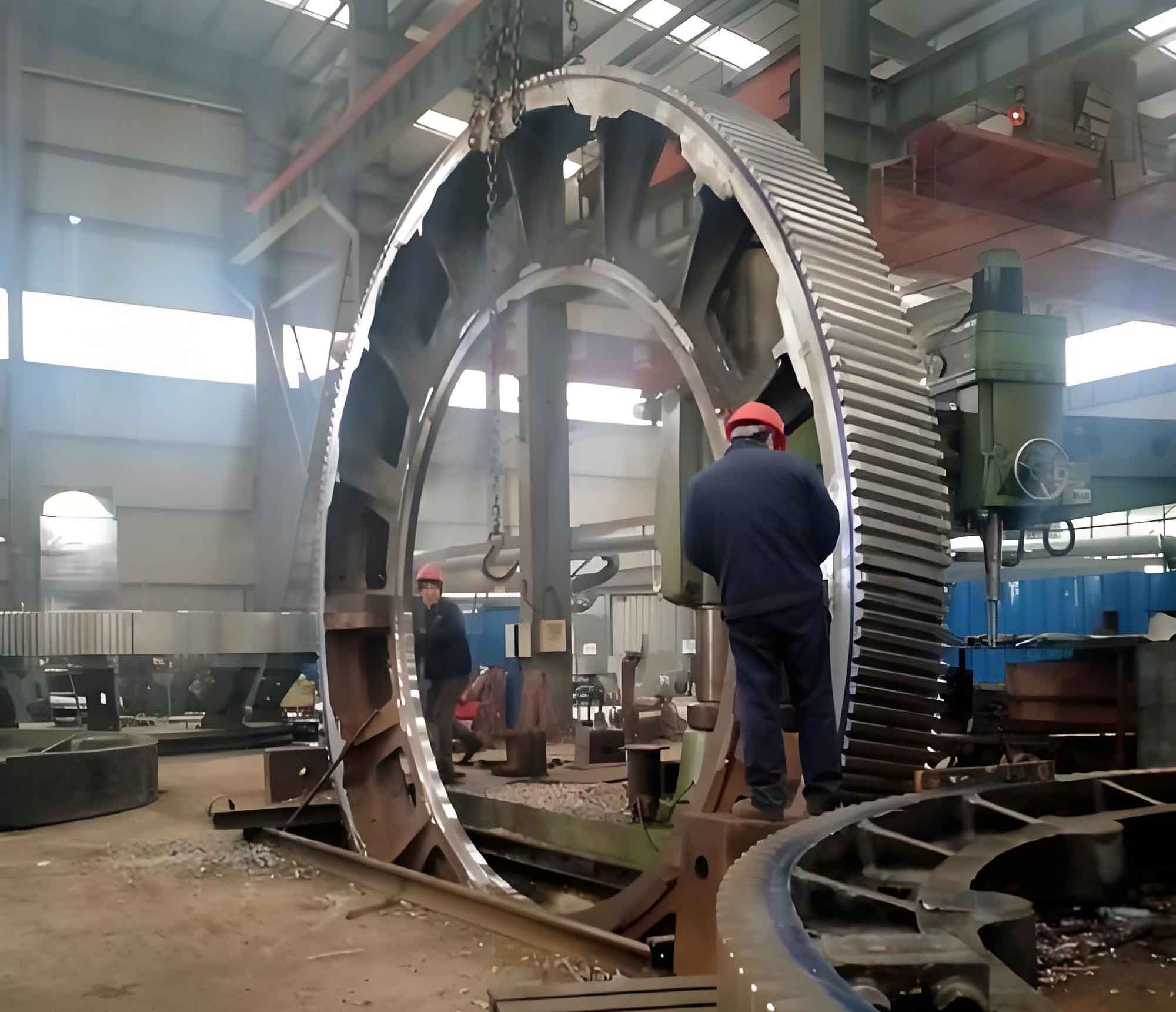
Industrial Validation: Large Press Gear Case Study
A 2,500-ton stamping press with a damaged main gear (da = 2,326 mm, mass = 4,709.8 kg) required remanufacturing. Parameters were unknown. Using dp = 28.96 mm balls:
| Measurement | Value |
|---|---|
| Axial Distance (H) | 128.68 mm |
| Transverse Distance (M) | 1,490.95 mm |
| Angular Projection (θ) | 0.021 rad |
| Transverse Module (Mt) | 16 mm |
| Tooth Count (Z) | 32 |
Calculated helix angle:
$$\beta = \arcsin \left( \frac{16 \cdot \cos \beta \cdot 32 \cdot 0.021}{2 \cdot \frac{128.68 – 28.96}{3}} \right) = 30^\circ 2′ 38”$$
Post-machining verification showed >85% contact length and >65% contact height, meeting operational standards.
Optimization and Error Mitigation
Factors influencing accuracy for large gears include:
| Factor | Impact | Mitigation Strategy |
|---|---|---|
| Surface Finish | Ball contact inconsistency | Polish measured flank areas |
| Platform Flatness | H measurement error | Use Grade 0 surface plates |
| Ball Diameter Tolerance | L and θ errors | Use precision balls (±0.001 mm) |
| β < 20° | High dH/dβ sensitivity | Use ≥5 balls; repeat measurements |
Final refinement used hobbing machine trials with initial β from calculations, reducing adjustment iterations by 70%.
Conclusion
This method provides accurate helix angle measurement for large gears using accessible metrology tools. Validated in industrial overhauls, it overcomes size limitations of traditional techniques. For large gears with β near 30°, measurement errors of 0.01 mm in H yield ≤33′ angle deviation—acceptable for most applications. The approach is scalable, with uncertainty reducible via ball count optimization and surface preparation. It is now standard for large gear maintenance across our facilities, having restored critical equipment like 2,500-ton presses to operational specifications.