
In this article, we explore the critical aspects of accuracy control in cycloidal-pinwheel transmission systems, which are fundamental to the performance of rotary vector reducers. As a key component in industrial robotics, the rotary vector reducer demands high precision, compact design, and robust dynamics. The focus here is on the cycloidal-pinwheel mechanism, as its transmission accuracy directly impacts the output shaft’s performance. We will delve into the research status, technological challenges, and future directions, leveraging tables and formulas to summarize key insights. Throughout, the term “rotary vector reducer” will be emphasized to underscore its centrality in modern mechanical systems.
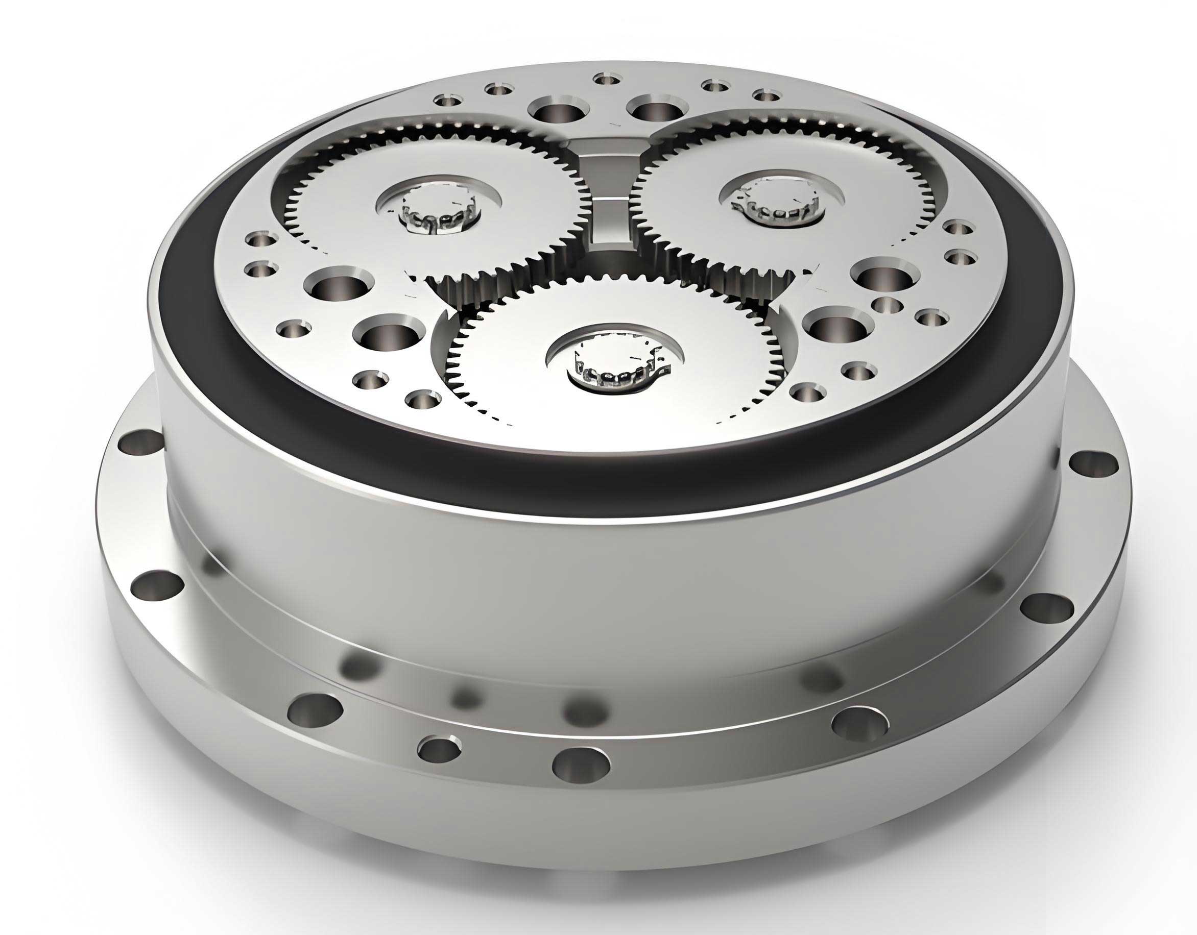
The rotary vector reducer, often abbreviated as RV reducer, is a precision gear system that combines a planetary gear mechanism with a cycloidal-pinwheel drive. Its advantages include high reduction ratios, compactness, stiffness, and load capacity, making it indispensable for robotic joints. However, achieving and maintaining transmission accuracy is a complex endeavor due to factors like manufacturing errors, assembly tolerances, and dynamic behaviors. In this work, we adopt a first-person perspective to review existing studies and identify unresolved technical issues, aiming to provide a comprehensive resource for researchers and engineers.
To set the stage, let’s consider the basic geometry of a cycloidal gear. The ideal tooth profile of a cycloidal gear, when meshing with a pinwheel, can be described mathematically. For a standard cycloidal gear, the parametric equations for the tooth profile are given by:
$$x = (R_p + r_p) \cos(\theta) – a \cos((z_p + 1)\theta)$$
$$y = (R_p + r_p) \sin(\theta) – a \sin((z_p + 1)\theta)$$
Here, \(R_p\) is the pinwheel radius, \(r_p\) is the pin radius, \(a\) is the eccentricity, \(z_p\) is the number of pins, and \(\theta\) is the rotation angle. However, in practice, perfect meshing is unattainable due to manufacturing imperfections, necessitating modifications or “modifications” to the tooth profile. This leads us to the core topic of cycloidal gear modification techniques.
Research Status on Cycloidal Gear Modification
In the realm of rotary vector reducers, cycloidal gear modification is paramount to compensate for errors and ensure proper lubrication and assembly. Theoretically, a standard cycloidal profile would result in zero backlash, but this is impractical. Therefore, various modification methods have been developed to introduce controlled backlash and improve meshing characteristics. We summarize the primary modification approaches in Table 1.
| Modification Method | Description | Key Parameters | Impact on Rotary Vector Reducer Performance |
|---|---|---|---|
| Offset Modification (移距修形) | Shifts the cycloidal profile radially inward or outward. | Offset distance \(\Delta r\) | Affects backlash and contact stress; crucial for precision in rotary vector reducers. |
| Equidistant Modification (等距修形) | Adjusts the equidistant curve of the cycloidal profile. | Equidistant amount \(\Delta a\) | Influences tooth thickness and meshing stiffness in rotary vector reducers. |
| Rotational Modification (转角修形) | Applies a rotational adjustment to the tooth profile. | Rotation angle \(\Delta \theta\) | Alters the phase of meshing, reducing transmission error in rotary vector reducers. |
| Combined Modification | Integrates multiple methods (e.g., offset + equidistant). | Optimized parameters \(\Delta r, \Delta a, \Delta \theta\) | Enhances load distribution and accuracy for high-performance rotary vector reducers. |
From our review, we note that modification techniques for rotary vector reducers have evolved significantly. Early work focused on simple offset or equidistant adjustments, but contemporary research emphasizes combined modifications to optimize meshing performance. For instance, an optimized combined modification might minimize the initial clearance while maximizing the number of teeth in contact. The optimization problem can be formulated as:
$$\min F(\Delta r, \Delta a, \Delta \theta) = w_1 \cdot \delta_{\text{clearance}} + w_2 \cdot \sigma_{\text{contact}} + w_3 \cdot \epsilon_{\text{error}}$$
where \(\delta_{\text{clearance}}\) is the backlash, \(\sigma_{\text{contact}}\) is the contact stress, \(\epsilon_{\text{error}}\) is the transmission error, and \(w_1, w_2, w_3\) are weighting factors. This approach is vital for rotary vector reducers used in precision robotics, where low backlash and high stiffness are required.
Moreover, the concept of “reverse bow tooth profile” has been proposed to improve contact conditions. This involves modifying the profile to create a slight convex shape, which reduces peak contact forces. The mathematical representation of such a profile can be derived by adding a correction term to the standard equations. For example, the modified profile might be:
$$x’ = x + \Delta x(\theta), \quad y’ = y + \Delta y(\theta)$$
where \(\Delta x(\theta)\) and \(\Delta y(\theta)\) are correction functions based on optimization results. These advancements underscore the importance of tailored modification strategies for rotary vector reducers.
Transmission Accuracy Control in Cycloidal-Pinwheel Systems
Beyond modification, the transmission accuracy of cycloidal-pinwheel systems in rotary vector reducers is influenced by manufacturing errors, assembly misalignments, and operational loads. We identify key sources of error and their effects in Table 2.
| Error Source | Description | Typical Magnitude | Effect on Rotary Vector Reducer |
|---|---|---|---|
| Tooth Profile Error | Deviation from ideal cycloidal shape due to machining. | Microns (μm) | Increases transmission error and vibration; critical for precision in rotary vector reducers. |
| Pitch Error | Variation in angular spacing between teeth. | Arcseconds | Causes non-uniform motion and backlash fluctuations in rotary vector reducers. |
| Eccentricity Error | Misalignment of gear centers. | Microns (μm) | Leads to periodic transmission error and reduced stiffness in rotary vector reducers. |
| Assembly Error | Inaccuracies in component positioning. | Millimeters or microns | Exacerbates other errors, affecting overall accuracy of rotary vector reducers. |
To quantify transmission accuracy, we often use the concept of transmission error, defined as the difference between the actual and theoretical output rotation. For a rotary vector reducer, the transmission error \(\Delta \phi\) can be modeled as a function of input angle \(\theta_i\) and error sources:
$$\Delta \phi(\theta_i) = \sum_{k=1}^{n} c_k \sin(k \theta_i + \phi_k)$$
where \(c_k\) and \(\phi_k\) are amplitude and phase coefficients derived from Fourier analysis of error contributions. This model helps in diagnosing and compensating for errors in rotary vector reducers.
Additionally, backlash or lost motion is a critical parameter. Backlash \(B\) in a cycloidal-pinwheel system can be estimated from modification parameters and manufacturing tolerances. An empirical formula is:
$$B \approx 2 \left( \Delta r + \frac{\Delta a}{R_p} \right) + \delta_{\text{mfg}}$$
where \(\delta_{\text{mfg}}\) accounts for manufacturing tolerances. Minimizing backlash without causing interference is a key challenge for rotary vector reducers, especially in robotic applications where positional accuracy is paramount.
Error measurement techniques are equally important. While coordinate measuring machines (CMMs) and laser interferometers are used, there is a growing need for specialized equipment for cycloidal gears in rotary vector reducers. We propose that future work should focus on developing integrated measurement systems that can directly assess tooth profile and pitch errors in situ.
Dynamics of Rotary Vector Reducers
The dynamic behavior of rotary vector reducers significantly influences their accuracy, noise, and longevity. In high-speed or high-load applications, vibrations can exacerbate transmission errors and lead to premature failure. Therefore, dynamic modeling and analysis are essential for optimizing rotary vector reducer design.
A simplified torsional dynamic model of a rotary vector reducer can be represented by a system of equations. Consider the system with input shaft, cycloidal gears, and output shaft. The equations of motion are:
$$J_i \ddot{\theta}_i + c_i (\dot{\theta}_i – \dot{\theta}_c) + k_i (\theta_i – \theta_c) = T_i$$
$$J_c \ddot{\theta}_c + c_c \dot{\theta}_c + k_c \theta_c + \sum_{j=1}^{N} F_j r_j = 0$$
$$J_o \ddot{\theta}_o + c_o \dot{\theta}_o + k_o \theta_o = T_o$$
Here, \(J_i, J_c, J_o\) are moments of inertia for input, cycloidal gear, and output; \(c_i, c_c, c_o\) are damping coefficients; \(k_i, k_c, k_o\) are stiffness coefficients; \(T_i, T_o\) are input and output torques; \(F_j\) is the contact force at tooth \(j\); and \(r_j\) is the effective radius. This model captures the essential dynamics but can be extended to include flexibilities and nonlinearities.
Contact forces between cycloidal teeth and pins are complex due to varying meshing stiffness. The meshing stiffness \(k_m\) can be approximated as a function of rotation angle \(\theta\):
$$k_m(\theta) = k_0 + \sum_{n=1}^{M} k_n \cos(n z_p \theta)$$
where \(k_0\) is the average stiffness and \(k_n\) are harmonic coefficients. This periodic stiffness excites vibrations, affecting the rotary vector reducer’s accuracy. We summarize key dynamic parameters in Table 3.
| Parameter | Symbol | Typical Range | Role in Rotary Vector Reducer Dynamics |
|---|---|---|---|
| Meshing Stiffness | \(k_m\) | 10^6 to 10^8 N/m | Determines natural frequencies and vibration modes in rotary vector reducers. |
| Damping Ratio | \(\zeta\) | 0.01 to 0.1 | Affects vibration attenuation and resonance peaks in rotary vector reducers. |
| Contact Force | \(F_c\) | 10^2 to 10^4 N | Influences wear, noise, and fatigue life of rotary vector reducers. |
| Natural Frequency | \(f_n\) | 100 to 1000 Hz | Critical for avoiding operational resonances in rotary vector reducers. |
Finite element analysis (FEA) and multi-body dynamics simulations are commonly used to study rotary vector reducer dynamics. For instance, virtual prototyping software like ADAMS can model the entire system, providing insights into forces, velocities, and accelerations. From our experience, such simulations reveal that optimizing the crankshaft and planetary carrier designs can reduce vibrations and improve the accuracy of rotary vector reducers.
Moreover, dynamic transmission error (DTE) is a key metric. DTE \(\Delta \phi_d(t)\) accounts for time-varying effects and can be expressed as:
$$\Delta \phi_d(t) = \Delta \phi_s + \Delta \phi_v(t)$$
where \(\Delta \phi_s\) is the static transmission error and \(\Delta \phi_v(t)\) is the vibrational component. Minimizing DTE is crucial for high-precision rotary vector reducers in robotics, as it directly impacts positioning accuracy.
Future Trends and Technical Challenges
Looking ahead, several trends and unresolved issues shape the development of cycloidal-pinwheel transmission for rotary vector reducers. Based on our analysis, we identify three main areas: design theory, manufacturing technology, and equipment innovation.
First, in design theory, there is a need for advanced modification techniques tailored to form grinding processes. Traditional generation grinding is being phased out due to inefficiency and limited flexibility. Form grinding allows for topological modifications but requires precise control. The optimization of modification parameters for form-ground cycloidal gears can be formulated as a multi-objective problem:
$$\text{Minimize: } \mathbf{F}(\mathbf{x}) = [f_1(\mathbf{x}), f_2(\mathbf{x}), f_3(\mathbf{x})]$$
$$\text{Subject to: } g_j(\mathbf{x}) \leq 0, \quad j=1,2,\dots,m$$
where \(\mathbf{x} = [\Delta r, \Delta a, \Delta \theta, \ldots]\), and objectives might include minimizing transmission error, maximizing load capacity, and ensuring lubrication gaps. This approach is essential for next-generation rotary vector reducers.
Second, manufacturing technology must address accuracy and consistency. Key challenges include reducing tooth profile errors and pitch errors through improved processes. We propose that error compensation algorithms based on real-time monitoring could enhance quality. For example, a feedback system could adjust grinding parameters based on in-process measurements, reducing errors in rotary vector reducer components.
Third, the development of specialized manufacturing equipment is critical. In particular, CNC form grinding machines for cycloidal gears are lacking. Such machines require integrated software for wheel dressing and profile generation. The wheel dressing process involves calculating the wheel profile \(W(u,v)\) that corresponds to the desired cycloidal tooth profile. The relationship can be described by:
$$W(u,v) = \mathbf{T} \cdot C(\theta) + \mathbf{D}$$
where \(\mathbf{T}\) is a transformation matrix, \(C(\theta)\) is the cycloidal curve, and \(\mathbf{D}\) is a correction vector for modifications. Implementing this in CNC systems would revolutionize the production of rotary vector reducers.
We summarize these challenges in Table 4, emphasizing their relevance to rotary vector reducers.
| Challenge Area | Specific Problem | Potential Solution | Importance for Rotary Vector Reducers |
|---|---|---|---|
| Design Theory | Optimization of topological modifications for form grinding. | Multi-objective algorithms and TCA/LTCA software. | Enhances meshing performance and accuracy of rotary vector reducers. |
| Manufacturing Technology | Control of tooth profile and pitch errors during grinding. | Error compensation and in-process measurement. | Reduces variability and improves consistency in rotary vector reducers. |
| Equipment Development | Lack of CNC form grinding machines for cycloidal gears. | Develop integrated CNC systems with dressing software. | Enables flexible, high-precision production of rotary vector reducers. |
| Dynamics and Vibration | Minimizing dynamic transmission error under load. | Improved damping designs and stiffness optimization. | Increases longevity and stability of rotary vector reducers in service. |
Additionally, the integration of digital twins and IoT technologies could enable predictive maintenance for rotary vector reducers, further enhancing reliability. We believe that collaborative research across academia and industry is vital to overcome these hurdles.
Conclusion
In conclusion, the accuracy control of cycloidal-pinwheel transmission in rotary vector reducers is a multifaceted field encompassing modification techniques, error analysis, and dynamic optimization. From our perspective, significant progress has been made in modification methods for generated gears, but challenges remain for form-ground gears. The transmission accuracy of rotary vector reducers is susceptible to manufacturing and assembly errors, necessitating advanced measurement and compensation strategies. Dynamically, rotary vector reducers exhibit complex behaviors that must be managed through design and simulation.
Looking forward, we emphasize the need for holistic approaches that combine design, manufacturing, and equipment innovation. Specifically, the development of CNC form grinding machines with topological modification capabilities will be a game-changer for rotary vector reducers. Moreover, ongoing research into dynamics and vibration control will ensure that rotary vector reducers meet the escalating demands of precision robotics and automation.
Throughout this article, we have highlighted the centrality of the rotary vector reducer in modern engineering systems. By addressing the technical problems outlined here, we can advance the performance and adoption of rotary vector reducers, contributing to the evolution of high-precision mechanical transmissions. We hope this work serves as a foundation for future investigations and practical advancements in the field.