
I present a complete methodology for the accurate design of offset non-orthogonal face gears. Face gears are widely used in high-power transmissions because they can transfer torque between intersecting or offset axes. Among all face gears, the offset non-orthogonal type is the most general and the most complex. Its tooth surfaces are asymmetric: one side is higher and the other side is lower. This asymmetry can increase the contact ratio and reduce the overall housing height. In this article, I derive the working and transition tooth surface equations of offset non-orthogonal face gears, calculate the minimum internal radius and maximum external radius under the geometric conditions of no undercutting and no tooth-tip sharpening, and build precise solid models by using the point-cloud method. I also perform assembly and kinematic simulations to verify the design. The results show that the proposed method is accurate and feasible for various face gears.
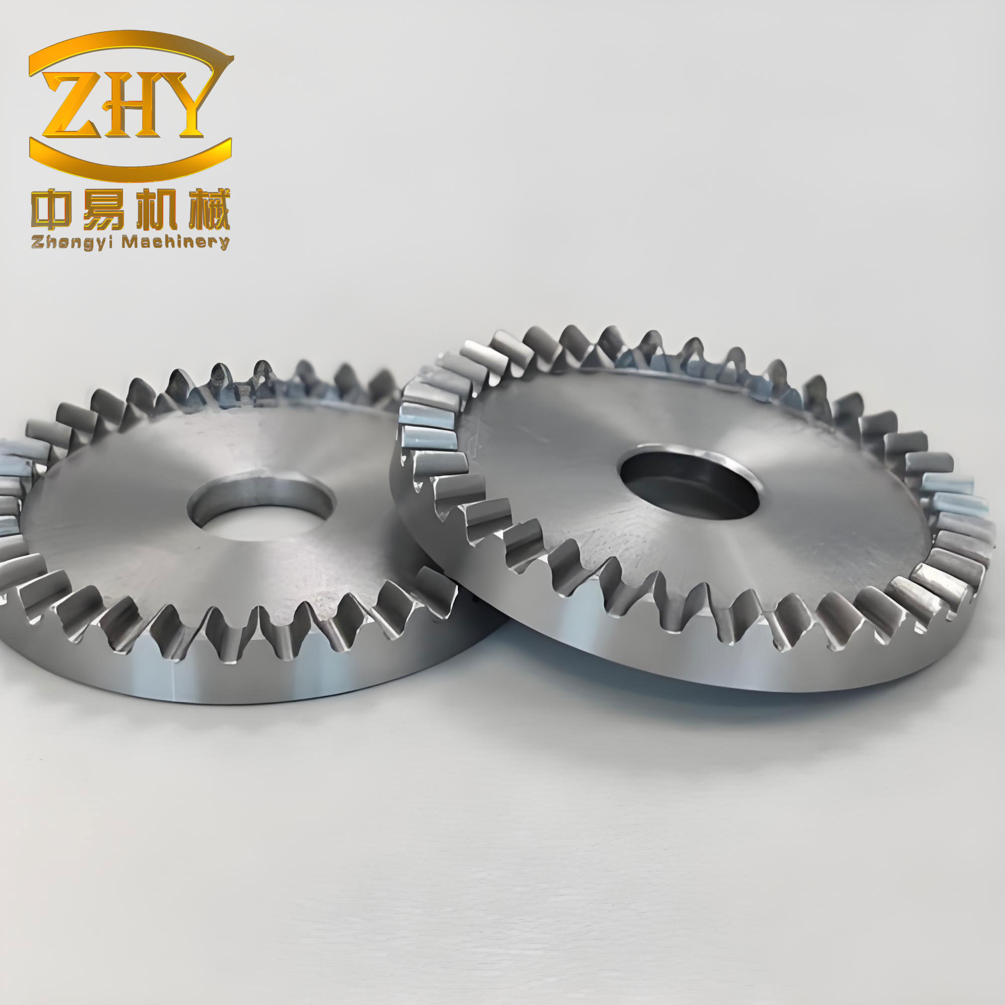
Face gears can be classified according to gear parameters, tooth profile, and the relative position of the pinion and the face gear. According to the position of the two axes, face gears can be divided into orthogonal, non-orthogonal, and offset types. The offset non-orthogonal face gears have two axes that are neither intersecting nor parallel. A shortest distance exists between the two axes, and the angle between them is not 90 degrees. This configuration gives the face gears unique meshing characteristics. Previous studies on orthogonal, non-orthogonal, and offset face gears have provided valuable insight, but the offset non-orthogonal face gears have received limited attention. In this work, I focus on the precise design of offset non-orthogonal face gears and their mating involute spur pinions.
For the design of face gears, the working tooth surface is usually determined as the envelope of the generating cutter surface. The cutter can be a shaper cutter, a worm, or a grinding wheel. In this article, I use a shaper cutter to generate the offset non-orthogonal face gears. The shaper cutter rotates with angular velocity \(\omega_s\), and the face gear blank rotates with angular velocity \(\omega_2\). The two axes have a shaft angle \(\gamma_m\) and an offset distance \(e\). The generating motion is similar to that of a conventional face gear, but the offset distance makes the tooth surface asymmetric.
I first establish the coordinate systems for the generating process. The coordinate system \(S_s(x_s, y_s, z_s)\) is rigidly connected to the shaper cutter. The coordinate system \(S_2(x_2, y_2, z_2)\) is rigidly connected to the offset non-orthogonal face gear. The coordinate system \(S_m(x_m, y_m, z_m)\) is the fixed frame of the machine tool. An auxiliary coordinate system \(S_p(x_p, y_p, z_p)\) is also used. The shaper cutter tooth surface is chosen so that the symmetry axis of the cutter tooth space is one of the coordinate axes. The shaper cutter tooth surface equation is written as:
$$
\mathbf{r}_s(u_s,\theta_s)=
\begin{bmatrix}
\pm r_{bs}\left[\sin(\theta_{os}+\theta_s)-\theta_s\cos(\theta_{os}+\theta_s)\right]\\
-r_{bs}\left[\cos(\theta_{os}+\theta_s)+\theta_s\sin(\theta_{os}+\theta_s)\right]\\
u_s\\
1
\end{bmatrix}
$$
where \(r_{bs}\) is the base radius of the shaper cutter, \(u_s\) and \(\theta_s\) are the tooth width and tooth height parameters, and \(\theta_{os}\) determines the tooth space width on the base circle:
$$
\theta_{os} = \frac{\pi}{2N_s} – \operatorname{inv}\alpha
$$
Here \(N_s\) is the number of shaper cutter teeth, and \(\alpha\) is the pressure angle. The unit normal vector of the shaper cutter tooth surface is:
$$
\mathbf{n}_s =
\frac{\frac{\partial \mathbf{r}_s}{\partial \theta_s} \times \frac{\partial \mathbf{r}_s}{\partial u_s}}
{\left|\frac{\partial \mathbf{r}_s}{\partial \theta_s} \times \frac{\partial \mathbf{r}_s}{\partial u_s}\right|}
=
\begin{bmatrix}
-\cos(\theta_{os}+\theta_s)\\
\mp \sin(\theta_{os}+\theta_s)\\
0
\end{bmatrix}
$$
In the above equations, the signs \(\pm\) and \(\mp\) correspond to the left and right sides of the shaper cutter tooth space. The family of shaper cutter surfaces in \(S_2\) is:
$$
\mathbf{r}_2(u_s,\theta_s,\phi_s) = M_{2s}(\phi_s)\mathbf{r}_s(u_s,\theta_s)
$$
The transformation matrix \(M_{2s}\) is the product of three matrices:
$$
M_{2s}(\phi_s)=M_{2p}M_{pm}M_{ms}
=
\begin{bmatrix}
M_{11} & M_{12} & -\sin\phi_2\sin\gamma_m & -e\cos\phi_2\\
M_{21} & M_{22} & -\cos\phi_2\sin\gamma_m & e\sin\phi_2\\
M_{31} & M_{32} & \cos\gamma_m & 0\\
0 & 0 & 0 & 1
\end{bmatrix}
$$
with the following entries:
$$
M_{11} = \cos\phi_2\cos\phi_s + \sin\phi_2\cos\gamma_m\sin\phi_s
$$
$$
M_{12} = -\cos\phi_2\sin\phi_s + \sin\phi_2\cos\gamma_m\cos\phi_s
$$
$$
M_{21} = -\sin\phi_2\cos\phi_s + \cos\phi_2\cos\gamma_m\sin\phi_s
$$
$$
M_{22} = \sin\phi_2\sin\phi_s + \cos\phi_2\cos\gamma_m\cos\phi_s
$$
$$
M_{31} = \sin\gamma_m\sin\phi_s
$$
$$
M_{32} = \sin\gamma_m\cos\phi_s
$$
The rotation angles of the shaper cutter and the face gear satisfy the transmission ratio relation:
$$
\phi_2 = \phi_s \frac{N_s}{N_2}
$$
where \(N_2\) is the number of teeth of the offset non-orthogonal face gear. The equation of the face gear working tooth surface in \(S_2\) is obtained from the envelope condition:
$$
\begin{cases}
\mathbf{r}_2(u_s,\theta_s,\phi_s) = M_{2s}(\phi_s)\mathbf{r}_s(u_s,\theta_s)\\
\Phi(u_s,\theta_s,\phi_s) = 0
\end{cases}
$$
The meshing equation \(\Phi = 0\) is:
$$
\Phi(u_s,\theta_s,\phi_s) = \mathbf{n}_s \cdot \mathbf{V}_s^{(s2)} = 0
$$
where \(\mathbf{V}_s^{(s2)}\) is the relative velocity of the shaper cutter surface with respect to the face gear surface, expressed in \(S_s\). This relative velocity has three components:
$$
V_{sx}^{(s2)} = -y_s(1-m_{2s}\cos\gamma_m) – z_s m_{2s}\sin\gamma_m\cos\phi_s + e m_{2s}\cos\gamma_m\sin\phi_s
$$
$$
V_{sy}^{(s2)} = x_s(1-m_{2s}\cos\gamma_m) + z_s m_{2s}\sin\gamma_m\sin\phi_s + e m_{2s}\cos\gamma_m\cos\phi_s
$$
$$
V_{sz}^{(s2)} = m_{2s}\sin\gamma_m(x_s\cos\phi_s – y_s\sin\phi_s) – m_{2s}e\sin\gamma_m
$$
Here \(m_{2s} = N_s/N_2\) is the transmission ratio between the face gear and the shaper cutter. Substituting the normal vector and the relative velocity into the meshing equation yields:
$$
\Phi(u_s,\theta_s,\phi_s) = r_{bs}(1-m_{2s}\cos\gamma_m) – u_s m_{2s}\sin\gamma_m \cos(\phi_s \pm \theta_s \pm \theta_{os}) \mp e m_{2s}\cos\gamma_m \sin(\phi_s \pm \theta_s \pm \theta_{os}) = 0
$$
Solving for \(u_s = z_s\) gives:
$$
u_s = z_s = \frac{r_{bs}(1-m_{2s}\cos\gamma_m) \mp h_s}{m_{2s}\sin\gamma_m \cos(\phi_s \pm \theta_s \pm \theta_{os})}
$$
where
$$
h_s = e m_{2s}\cos\gamma_m \sin(\phi_s \pm \theta_s \pm \theta_{os})
$$
Substituting the above expressions into the family of shaper cutter surfaces gives the working tooth surface of the offset non-orthogonal face gear in \(S_2\):
$$
\mathbf{r}_2(\theta_s,\phi_s)=
\begin{bmatrix}
M_{11}x_s + M_{12}y_s – z_s\sin\phi_2\sin\gamma_m – e\cos\phi_2\\
M_{21}x_s + M_{22}y_s – z_s\cos\phi_2\sin\gamma_m – e\sin\phi_2\\
M_{31}x_s + M_{32}y_s – z_s\cos\gamma_m\\
1
\end{bmatrix}
$$
For accurate modeling, I transform the working tooth surface from \(S_2\) to a reference coordinate system \(S_c\). The transformation is performed by rotating \(S_2\) about the \(x_2\) axis by \(\gamma_m\) and then translating it along the \(z_2\) axis by \(h\sin\gamma_m\). The transformation matrix is:
$$
M_{c2} =
\begin{bmatrix}
1 & 0 & 0 & 0\\
0 & \cos\gamma_m & \sin\gamma_m & h\\
0 & -\sin\gamma_m & \cos\gamma_m & h\cot\gamma_m\\
0 & 0 & 0 & 1
\end{bmatrix}
$$
The distance \(h\) is:
$$
h = \frac{m N_s}{2} – m h_a^*
$$
where \(m\) is the module and \(h_a^*\) is the addendum coefficient of the face gear. Thus, the working tooth surface in \(S_c\) is:
$$
\mathbf{r}_c(\theta_s,\phi_s) = M_{c2}\mathbf{r}_2(\theta_s,\phi_s)
$$
The transition tooth surface of the offset non-orthogonal face gear is generated by the fillet of the shaper cutter. The fillet is formed by the intersection line \(L\) between the addendum cylinder of the shaper cutter and the working tooth surface. The maximum tooth height parameter of the shaper cutter is:
$$
\theta_s^* = \frac{\sqrt{r_{as}^2 – r_{bs}^2}}{r_{bs}}
$$
where \(r_{as}\) is the addendum radius of the shaper cutter:
$$
r_{as} = \frac{m N_s}{2} + h_{as}^* m
$$
and \(h_{as}^*\) is the addendum coefficient of the shaper cutter. The transition tooth surface in \(S_2\) is:
$$
\mathbf{r}_2^*(u_s,\phi_s) = M_{2s}(\phi_s)\mathbf{r}_s(u_s,\theta_s^*)
$$
and in \(S_c\) it becomes:
$$
\mathbf{r}_c^*(u_s,\phi_s) = M_{c2}\mathbf{r}_2^*(u_s,\phi_s)
$$
The intersection line between the transition surface and the working surface is their common tangent line \(L^*\). This line satisfies the meshing equation with \(\theta_s = \theta_s^*\). Its equation in \(S_2\) is:
$$
\mathbf{r}_{2L^*}(\phi_s) = M_{2s}(\phi_s)\mathbf{r}_{sL^*}(\phi_s)
$$
and in \(S_c\):
$$
\mathbf{r}_{cL^*}(\phi_s) = M_{c2}\mathbf{r}_{2L^*}(\phi_s)
$$
The tooth width of the offset non-orthogonal face gear must be designed carefully. The minimum internal radius \(R_1\) is determined by the undercutting limit. The limit line \(K_1\) on the shaper cutter surface forms singular points on the face gear tooth surface. The condition is:
$$
\begin{cases}
\mathbf{r}_s = \mathbf{r}_s(u_s,\theta_s)\\
\Phi(u_s,\theta_s,\phi_s) = 0\\
\Delta_2 = 0
\end{cases}
$$
The Jacobian determinant \(\Delta_2\) is:
$$
\Delta_2 =
\begin{vmatrix}
\frac{\partial \Phi}{\partial u_s} & \frac{\partial \Phi}{\partial \theta_s} & \frac{\partial \Phi}{\partial \phi_s}\frac{d\phi_s}{dt}\\
\frac{\partial x_s}{\partial u_s} & \frac{\partial x_s}{\partial \theta_s} & \omega_s^{(s)} V_{sx}^{(s2)}\\
\frac{\partial z_s}{\partial u_s} & \frac{\partial z_s}{\partial \theta_s} & \omega_s^{(s)} V_{sz}^{(s2)}
\end{vmatrix}
= 0
$$
The limit point is obtained by combining the above equations with \(\theta_s = \theta_s^*\). After transforming the limit point to \(S_c\), its coordinates are \((x_{kc}, y_{kc}, z_{kc})\). The minimum internal radius is:
$$
R_1 = \sqrt{x_{kc}^2 + z_{kc}^2}
$$
Because the two sides of the offset non-orthogonal face gear are asymmetric, two values are obtained: \(R_1^L\) and \(R_1^R\). The larger one is selected:
$$
R_1 = \max(R_1^L, R_1^R)
$$
The maximum external radius \(R_2\) is determined by tooth-tip sharpening. The tooth thickness at the tip becomes zero when the left and right tooth surfaces meet. The condition is:
$$
\begin{cases}
x_c^L(\theta_s^L,\phi_s^L) = x_c^R(\theta_s^R,\phi_s^R)\\
z_c^L(\theta_s^L,\phi_s^L) = z_c^R(\theta_s^R,\phi_s^R)\\
y_c^L(\theta_s^L,\phi_s^L) = 0\\
y_c^R(\theta_s^R,\phi_s^R) = 0
\end{cases}
$$
Solving these equations gives the critical points. The maximum external radius is:
$$
R_2 = \sqrt{x_{Lc}^2 + z_{Lc}^2} = R_2^L = \sqrt{x_{Rc}^2 + z_{Rc}^2} = R_2^R
$$
The tooth width \(B\) is then:
$$
B = R_2 – R_1
$$
For high-power transmissions, a dimensionless coefficient \(c\) is used:
$$
c = \frac{B}{m} = \frac{R_2 – R_1}{m}
$$
In general, \(c \ge 10\) is required. If \(c \lt 10\), the number of teeth and the shaft angle can be increased, or the offset distance can be reduced.
The design parameters used in this study are summarized in the following table.
| Parameter | Value |
|---|---|
| Module \(m\) (mm) | 3 |
| Number of shaper cutter teeth \(N_s\) | 25 |
| Number of pinion teeth \(N_1\) | 22 |
| Pressure angle \(\alpha\) (deg) | 20 |
| Number of face gear teeth \(N_2\) | 115 |
| Shaper cutter addendum coefficient \(h_{as}^*\) | 1.25 |
| Pinion addendum coefficient \(h_{a1}^*\) | 1 |
| Face gear addendum coefficient \(h_a^*\) | 1 |
| Offset distance \(e\) (mm) | 20 |
| Shaft angle \(\gamma_m\) (deg) | 105 |
| Face gear internal radius \(R_1\) (mm) | 176.02 |
| Face gear external radius \(R_2\) (mm) | 206.05 |
For accurate modeling, I use the point-cloud method. This method is more precise than the cross-section lofting method, and its accuracy can be easily controlled. The point-cloud method is especially suitable for offset non-orthogonal face gears, which are used in high-precision applications such as helicopter transmissions. The modeling procedure for a single tooth is as follows.
First, I input the basic parameters of the face gear and the shaper cutter, such as \(m\), \(N_s\), \(\alpha\), \(N_2\), \(h_{as}^*\), \(h_a^*\), \(e\), and \(\gamma_m\). Then I calculate \(r_{bs}\), \(m_{2s}\), \(\operatorname{inv}\alpha\), \(\theta_{os}\), \(h\), \(\theta_s^*\), and \(r_{as}\). Next, I solve for \(R_1\) and \(R_2\) and select the tooth width \(B\). The two variables of the working tooth surface are \(\theta_s\) and \(\phi_s\). I discretize the tooth width \(B\) into \(j\) intervals. For each interval \(B_j\), I solve the nonlinear equations:
$$
\begin{cases}
x_{2c}^2 + z_{2c}^2 = B_j^2\\
y_c = 0
\end{cases}
$$
This gives \(j\) pairs of \(\phi_{sj}\) and \(\theta_{sj}\). Then I discretize the interval \([\theta_{sj}, \theta_s^*]\) into \(i\) parts to obtain \(\theta_{sji}\). Substituting \(\theta_{sji}\) into the nonlinear equation \(x_{2c}^2 + z_{2c}^2 = B_j^2\) gives \(\phi_{sj}’\). Finally, substituting \((\theta_{sji}, \phi_{sj}’)\) into the equation of \(\mathbf{r}_c\) gives \(i \times j\) discrete points on the left and right working tooth surfaces in \(S_c\). The larger the values of \(i\) and \(j\), the more accurate the model.
For the transition tooth surface, the two variables are \(u_s\) and \(\phi_s\). I first solve the nonlinear equation \(x_{2c}^* + z_{2c}^* = B_j^2\) to obtain the minimum values \(\phi_{sj\min}^*\). Then I solve:
$$
\begin{cases}
x_{2c}^* + z_{2c}^* = B_j^2\\
y_c^* = -r_{as}
\end{cases}
$$
This gives the maximum values \(\phi_{sj\max}^*\). I discretize the interval \([\phi_{sj\min}^*, \phi_{sj\max}^*]\) into \(i\) parts to obtain \(\phi_{sji}^*\). Substituting \(\phi_{sji}^*\) into \(x_{2c}^* + z_{2c}^* = B_j^2\) gives \(u_{sj}^*\). Then \((\boldsymbol{u}_{sj}^*, \phi_{sji}^*)\) is substituted into the transition surface equation to obtain \(j \times i\) discrete points on the left and right transition surfaces in \(S_c\). The common tangent line \(L^*\) is obtained by substituting the \(j\) values of \(\phi_{sj}’\) into the corresponding equation. This line connects the working surface and the transition surface smoothly.
I implemented the above procedure in MATLAB. The resulting single-tooth model of the offset non-orthogonal face gear for \(\gamma_m \gt 90^\circ\) shows no undercutting and no tooth-tip sharpening. The intersection between the working tooth surface and the transition tooth surface is their common tangent line. This confirms the correctness of the mathematical derivation. For \(\gamma_m \lt 90^\circ\), I also obtained a valid single-tooth model by using the corresponding minimum internal radius and maximum external radius. In one case with \(\gamma_m = 75^\circ\), \(R_1 = 172.7\) mm and \(R_2 = 203.7\) mm.
After the point-cloud coordinates are calculated, I import the data files into a three-dimensional CAD environment. I use UG to build the solid model. First, I draw the blank sketch in the reference coordinate system \(S_c\). Then I revolve the sketch to obtain the gear blank. Using point-cloud surface construction operations, I create the working tooth surfaces and the transition tooth surfaces. Finally, I generate the complete three-dimensional model of the offset non-orthogonal face gear. The same procedure is applied to both \(\gamma_m \gt 90^\circ\) and \(\gamma_m \lt 90^\circ\). The models are free from interference and have the correct tooth geometry.
The mating pinion is an involute spur gear. Although many CAD systems can generate involute gears directly, their precision is often insufficient, especially for the transition surface at the tooth root. In face gear drives, the pinion is the driving member and must transmit torque accurately. Therefore, the pinion tooth surface must also be modeled precisely. I use a shaper cutter to generate the pinion, and I derive both the working tooth surface and the transition tooth surface.
The working tooth surface of the pinion is obtained by changing the subscript \(s\) to \(1\) in the shaper cutter equation. However, for precise modeling, I establish the tooth surface equation with the symmetry axis of the tooth profile as the \(y\) axis. The working tooth surface equation is:
$$
\mathbf{r}_1(u_1,\theta_1)=
\begin{bmatrix}
\pm r_{b1}(\sin\Psi – \theta_1\cos\Psi)\\
r_{b1}(\cos\Psi + \theta_1\sin\Psi)\\
u_1\\
1
\end{bmatrix}
$$
where
$$
\Psi = \theta_{c1} + \theta_1 – \phi_{c1}
$$
and
$$
\phi_{c1} = \frac{\pi}{N_1}
$$
Here \(r_{b1}\) is the base radius of the pinion, \(\theta_{c1}\) is the half tooth space angle on the pitch circle, and \(\phi_{c1}\) is half of the angular pitch. The transition surface of the pinion is generated by the addendum cylinder of the shaper cutter. Assuming the shaper cutter pitch circle rolls without slipping on the pinion pitch circle, the transition surface equation is:
$$
\mathbf{r}_1^*(u_1,\phi_1)=
\begin{bmatrix}
-(r_{p1}+r_{ps})\sin\psi_1 + r_{as}\cos\psi_s\\
(r_{p1}+r_{ps})\cos\psi_1 – r_{as}\sin\psi_s\\
u_1\\
1
\end{bmatrix}
$$
where
$$
\psi_1 = \phi_{c1} – \phi_1
$$
$$
\psi_s = \frac{\pi}{2} – \psi_1 – (\Xi_s – \phi_s)
$$
$$
\Xi_s = \frac{\pi}{N_s} – \theta_{os} – \theta_s^* + \arctan\theta_s^*
$$
and
$$
\phi_1 = \phi_s \frac{N_s}{N_1}
$$
Here \(r_{p1}\) and \(r_{ps}\) are the pitch radii of the pinion and the shaper cutter, respectively. The pinion transition surface is symmetric about \(y_1 = 0\). I discretize the tooth width \(B\) into \(j\) parts for \(u_1\). For the working tooth surface, I discretize \(\theta_1\) from \(0\) to its maximum value at the tooth tip into \(i\) parts. Substituting \((u_{1j}, \theta_{1i})\) into the working tooth surface equation gives \(i \times j\) discrete points. For the transition surface, I discretize \(\phi_s\) from its minimum value to its maximum value \(\phi_{s\max} = \Xi_s\) into \(i\) parts, and I use the same \(u_{1j}\). Substituting \((u_{1j}, \phi_{1i})\) into the transition surface equation gives another \(i \times j\) discrete points. I implemented this procedure in MATLAB and obtained a precise single-tooth model of the involute spur pinion. Then I imported the point-cloud data into UG and built the complete solid model of the pinion.
With the precise models of the offset non-orthogonal face gear and the pinion, I performed assembly in UG. The pinion tooth width was set to \(B = 30\) mm. The offset distance and shaft angle were the same as those in the design table. The assembly had no backlash and a standard clearance of \(0.25m = 0.75\) mm. The fact that the assembly was successful without any interference or incorrect clearance confirms the accuracy of the design.
Next, I carried out kinematic simulation in UG. I added links, revolute joints, and gear coupling constraints. The pinion was set as the driving member. I applied a driving angular velocity to the pinion and solved the motion. One purpose of the simulation was to check for interference. I selected the pinion and the face gear as the first and second groups, set the mode to precise solid, and set the clearance to zero. The simulation showed no interference. Another purpose was to verify the angular velocity ratio. I applied an angular velocity of \(35^\circ/\text{s}\) to the pinion and ran the simulation for \(5\) s with \(150\) steps. The angular velocity curves of the pinion and the face gear were constant, and their ratio exactly matched the designed transmission ratio. This further confirms the correctness of the design method.
In summary, I have developed a complete method for the accurate design of offset non-orthogonal face gears. The method includes the derivation of the working and transition tooth surface equations, the calculation of the minimum internal radius and maximum external radius, the construction of precise solid models using the point-cloud method, and the verification of the design by assembly and kinematic simulation. The results show that the offset non-orthogonal face gears have no undercutting or tooth-tip sharpening, the working and transition surfaces are tangent to each other, and the transmission ratio is satisfied during meshing. The proposed method can be applied to various face gears with different transmission forms.
The following table summarizes the key equations used in this work.
| Item | Equation |
|---|---|
| Shaper cutter tooth surface | \(\mathbf{r}_s(u_s,\theta_s)\) |
| Shaper cutter unit normal | \(\mathbf{n}_s\) |
| Face gear family of surfaces | \(\mathbf{r}_2(u_s,\theta_s,\phi_s) = M_{2s}(\phi_s)\mathbf{r}_s(u_s,\theta_s)\) |
| Meshing equation | \(\Phi(u_s,\theta_s,\phi_s) = \mathbf{n}_s \cdot \mathbf{V}_s^{(s2)} = 0\) |
| Face gear working surface in \(S_2\) | \(\mathbf{r}_2(\theta_s,\phi_s)\) |
| Face gear working surface in \(S_c\) | \(\mathbf{r}_c(\theta_s,\phi_s) = M_{c2}\mathbf{r}_2(\theta_s,\phi_s)\) |
| Maximum shaper cutter tooth height parameter | \(\theta_s^* = \sqrt{r_{as}^2 – r_{bs}^2} / r_{bs}\) |
| Face gear transition surface in \(S_c\) | \(\mathbf{r}_c^*(u_s,\phi_s) = M_{c2}M_{2s}(\phi_s)\mathbf{r}_s(u_s,\theta_s^*)\) |
| Minimum internal radius | \(R_1 = \max(R_1^L, R_1^R)\) |
| Maximum external radius | \(R_2 = \sqrt{x_{Lc}^2 + z_{Lc}^2} = \sqrt{x_{Rc}^2 + z_{Rc}^2}\) |
| Tooth width coefficient | \(c = (R_2 – R_1)/m\) |
| Pinion working surface | \(\mathbf{r}_1(u_1,\theta_1)\) |
| Pinion transition surface | \(\mathbf{r}_1^*(u_1,\phi_1)\) |
The point-cloud method used in this work provides a high degree of accuracy. By increasing the number of discrete points in both the tooth width and tooth height directions, the model can be made arbitrarily close to the theoretical tooth surface. The same approach can be extended to other types of face gears, including orthogonal, non-orthogonal, and asymmetric face gears. The assembly and kinematic simulation results confirm that the design is correct and that the offset non-orthogonal face gears can operate without interference. The angular velocity ratio satisfies the transmission ratio relation, which is essential for high-power face gear drives.
In conclusion, I have shown that the offset non-orthogonal face gears can be designed accurately by using the proposed mathematical model and the point-cloud modeling technique. The working tooth surface and the transition tooth surface are derived analytically. The minimum internal radius and maximum external radius are calculated from the no-undercutting and no-sharpening conditions. The precise solid models are built in UG. The assembly and kinematic simulation verify the design. This method provides a feasible and accurate way to design various face gears for demanding applications.