
1. Introduction
Spiral bevel gear plays crucial role in mechanical transmission systems, enabling the transfer of motion and power between intersecting or skew shafts. These gears offer several advantages such as high contact ratio, strong load-carrying capacity, smooth transmission, and low noise. However, their complex three-dimensional geometry and unique manufacturing requirements pose significant challenges in terms of accurate modeling and efficient production.
1.1 Background and Significance
The study of spiral bevel gear has been an area of active research due to their widespread applications in various industries. Different types of spiral bevel gear, including circular arc bevel gear, extended epicycloid bevel gear, and logarithmic spiral bevel gear, have been explored. However, each type has its own limitations in terms of tooth geometry and manufacturing processes. For example, some gear may not have a true conical spiral tooth profile, and others may face difficulties in mass production due to complex machining requirements.
Metal powder injection molding (MIM) is a promising manufacturing technique that has the potential to overcome these challenges. It allows for the production of complex-shaped metal components with high precision and can be suitable for mass production. In the context of spiral bevel gear, MIM offers an opportunity to produce gear with accurate tooth profiles and in large quantities, reducing production costs and lead times.
1.2 Objectives of the Study
The main objectives of this research are as follows:
- To develop an accurate mathematical model for a new type of spiral bevel gear, namely the equal-distance spiral bevel gear.
- To perform a detailed analysis of the gear’s meshing characteristics and transmission performance.
- To demonstrate the feasibility of manufacturing equal-distance spiral bevel gear using the MIM process.
2. Design and Modeling of Equal-Distance Spiral Bevel Gear
2.1 Design Parameters
The design of the equal-distance spiral bevel gear is based on specific geometric parameters. As shown in Table 1, these parameters include the number of teeth, shaft angle, pitch cone angle, module, midpoint spiral angle, tooth width, and pressure angle for both the pinion and spiral bevel gear.
| Name | Rotation Direction | Number of Teeth, N | Shaft Angle, / | Pitch Cone Angle, / | Module, m/mm | Midpoint Spiral Angle, / | Tooth Width, b/mm | Pressure Angle, a/) |
|---|---|---|---|---|---|---|---|---|
| Pinion | Left | 16 | 90 | 34.824 | 0.905 | 30 | 5 | 20 |
| Gear | Right | 23 | 90 | 55.176 | 0.905 | 30 | 5 | 20 |
2.2 Tooth Surface Mathematical Modeling
2.2.1 Spherical Involute
The tooth profile of the equal-distance spiral bevel gear is based on the spherical involute. The formation process of the spherical involute involves the pure rolling of a circular plane on a base cone . A right-handed coordinate system is established with the cone axis as the -axis and is fixed to the cone. Another right-handed coordinate system is attached to the circular plane .
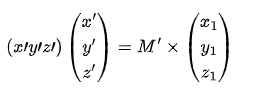
The coordinate transformation matrix from to is given by:
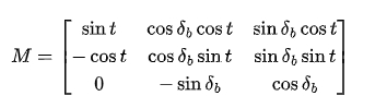
where is the rotation angle of the circular plane and is the cone angle of the base cone .
The coordinates of a point on the circular plane in the moving coordinate system are given by:
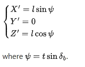
Using the coordinate transformation matrix , the coordinates of the point in the fixed coordinate system can be obtained, and the parametric equation of the spherical involute is:
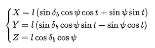
where is the cone distance at the starting point of the spherical involute.
2.2.2 Equal-Distance Conical Spiral Line
The tooth direction line of the equal-distance spiral bevel gear is an equal-distance conical spiral line. It can be considered as the combination of two motions: a uniform motion along an Archimedes spiral in the horizontal plane and a uniform motion in the vertical direction.
The equation of the equal-distance conical spiral line in a rectangular coordinate system with the cone angle and the equal-distance lead is given by:
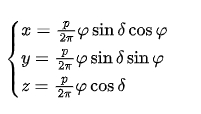
where is the rotation angle of the Archimedes spiral around the -axis.
The equal-distance lead can be determined based on the design parameters of spiral bevel gear. For example, for a given midpoint spiral angle , the equal-distance lead for the pinion and the gear can be calculated as mm and mm, respectively.
2.2.3 Tooth Surface Equation
The tooth surface of the equal-distance spiral bevel gear can be represented by multiple spherical involutes distributed along the equal-distance conical spiral line. By adjusting the starting cone distance of the spherical involute or rotating it around the -axis along the equal-distance conical spiral line, different tooth profiles can be obtained.
The parametric equation of the tooth surface can be derived by first obtaining the parametric equation of a spherical involute in a moving coordinate system and then applying the coordinate transformation matrix. The final tooth surface equation is given by:
where is the coordinate transformation matrix for rotation around the -axis and are the coordinates of a point on the spherical involute in the moving coordinate system.
3. Precise Modeling of Equal-Distance Spiral Bevel Gear
3.1 MATLAB for Discrete Point Calculation
Due to the complex spatial spiral surface of the equal-distance spiral bevel gear’s tooth surface, it is difficult to ensure accuracy when using three-dimensional software like UG for direct modeling. Therefore, the established tooth surface equation is used in MATLAB to write a program. By setting an appropriate step size for calculation, the discrete point coordinates of the tooth surface can be obtained. A smaller step size in the program leads to more accurate tooth surface modeling.
3.2 3D Modeling in UG
The discrete point coordinates of the tooth surface saved in a txt format are imported into UG. Using the fitting surface tool, the discrete points are fitted into a smooth surface to obtain a set of tooth surfaces. Subsequently, the top cone surface, root cone surface, front cone surface, and back cone surface of spiral bevel gear tooth are established. Through commands such as trimming and sewing, a single gear tooth of the equal-distance spiral bevel gear is obtained. After that, the fillet at the tooth root transition part can be optimized with a variable radius, and then the single tooth is circularly arrayed to obtain the precise model of the equal-distance spiral bevel gear.
4. Dynamic Meshing Simulation Analysis
4.1 Finite Element Model Establishment
The ANSYS Workbench is used to simulate the meshing process of the equal-distance spiral bevel gear to obtain the tooth surface contact area, rotational speed, and transmission error during transmission, thereby determining whether spiral bevel gear meets the actual transmission requirements.
- Mesh Generation: Due to the complex geometry of spiral bevel gear teeth, Hypermesh is used to divide the three-dimensional model of spiral bevel gear. A hexahedral mesh with a small computational amount, fast convergence speed, and small deformation amount is selected, and the Solid186 entity reduced integration unit with intermediate nodes is chosen as the mesh unit.
- Material Properties: To ensure the authenticity of the simulation results, the Fe8Ni material used in the subsequent metal powder injection molding experiment is selected for material property assignment. The density, elastic modulus, and Poisson’s ratio of Fe8Ni are 7600 kg/m², 190 GPa, and 0.28, respectively.
- Boundary Conditions and Working Conditions: For the small-sized transmission device where the metal powder injection molded equal-distance spiral bevel gear is mainly used, a constant rotational speed of 3000 r/min is given to the pinion, and a load of 15 N·M is applied to spiral bevel gear to analyze the contact performance of the equal-distance spiral bevel gear under load.
4.2 Simulation Results Analysis
4.2.1 Tooth Surface Contact Area
Based on the post-processing of ANSYS Workbench, the tooth surface contact area during transmission is extracted to study the tooth surface contact situation during the meshing transmission of the equal-distance spiral bevel gear. The contact area is approximately elliptical and located near the middle of the tooth surface, which is in accordance with the theoretical contact area predicted by the Hertz contact theory. This indicates that the equal-distance spiral bevel gear meets the requirements of the tooth surface contact area during transmission and has a good contact condition.
4.2.2 Rotational Speed and Transmission Error
The ideal (theoretical) rotational speed of the driven gear can be calculated according to the transmission ratio as 218.55 rad/s. The actual rotational speed of the driven gear obtained from the post-processing of ANSYS Workbench fluctuates near the ideal rotational speed and has a similar variation pattern. This shows that the actual transmission of the equal-distance spiral bevel gear is relatively stable.
The transmission error, which is the difference between the actual and theoretical rotational angles of the driven gear during the meshing transmission process, is calculated. The transmission error of the equal-distance spiral bevel gear fluctuates near the ideal transmission error of 0 rad and has a certain pattern, and the transmission error is less than rad. This indicates that the dynamic meshing performance of the equal-distance spiral bevel gear is good, with stable transmission and high transmission efficiency.
5. Metal Powder Injection Molding Process for Gear Production
5.1 Material Selection
- Metal Powder: Fe8Ni alloy powder is selected with an average particle size of 3.95 μm and a tapped density of 4.35 g/cm³. The particle size of the metal powder used in the MIM process is generally between 0.5 – 20.0 μm, and the median diameter is between 4.0 – 8.0 μm.
- Binder: A binder composed of 90% POM (polyformaldehyde), 6% HDPE (high-density polyethylene), and 4% SA (stearic acid) is selected. POM is chosen because it can quickly soften when heated and harden when cooled without changing its properties. HDPE is used as a skeleton structure to maintain the shape of the blank during degreasing, and SA is used as a surfactant to promote the fluidity of the feed during injection.
5.2 Mixing and Pelletizing
The mixing temperature is set between 175 – 185°C due to the decomposition temperature of POM and the melting temperature of HDPE. A single-screw mixing and pelletizing integrated machine of model M – H – 10L – DCSS – H is used with a rotation speed of 30 r/min and a mixing time of 30 min. The resulting granular feed is shown in Figure [X].
5.3 Injection Molding, Degreasing, and Sintering
- Injection Molding: Based on the three-dimensional model of the equal-distance spiral bevel gear, the electrode of the gear is machined in a five-axis linked machining center, and the corresponding cavity is discharged in a precision spark machine. Then, a mold is designed, and the equal-distance spiral bevel gear green body (using Fe8Ni material) is injection molded in an injection machine with an injection temperature of 190°C, a pressure of 50 MPa, and a speed of 50 mm/s.
- Degreasing: The degreasing process is carried out in a degreasing furnace with an atmosphere as a catalyst. The green body is first heated to 120°C for catalytic degreasing and then to 600°C for 120 min to remove the polyethylene and stearic acid in the binder.
- Sintering: The degreased gear is placed in a vacuum sintering furnace with a sintering atmosphere of and a sintering temperature of 1260°C.
The final metal powder injection molded equal-distance spiral bevel gear is obtained, and the successful rotation demolding of the gear verifies the accuracy of the gear modeling and the feasibility of the MIM process for spiral bevel gear production.
6. Conclusion
- The accurate modeling of the equal-distance spiral bevel gear is achieved by programming the tooth surface mathematical model in MATLAB to obtain discrete point data and then using UG reverse engineering. This method effectively guarantees the accuracy of the model.
- During the meshing transmission of the equal-distance spiral bevel gear, the tooth surface contact area is approximately elliptical and located near the middle of the tooth surface. The fluctuations of the driven gear’s rotational speed and transmission error are regular, and the transmission error is less than rad, verifying the stable transmission and high efficiency of spiral bevel gear, as well as its good meshing performance.
- The first successful trial production of equal-distance spiral bevel gear using the MIM process validates the accuracy of spiral bevel gear design and modeling and the feasibility of using the MIM process for actual production. This achievement realizes the mass production of small cone angle spiral bevel gear, significantly reducing production costs and manufacturing cycles.
In summary, the research on equal-distance spiral bevel gear presented in this article provides a comprehensive understanding of their design, modeling, analysis, and manufacturing processes, opening up new possibilities for the application of spiral bevel gear in various industries.