
Parametric modeling of bevel gear is a method of quickly establishing gear models with the help of computer-aided design. Both spur bevel gear and spiral bevel gear belong to the category of bevel gear, and the parameterization modeling process of their tooth blanks has similarities. The difference is the distribution of their teeth on the tooth blanks. The teeth of spur bevel gear are vertically distributed along the tooth blanks, while the teeth of spiral bevel gear are distributed in a certain arc along the tooth blanks. It is precisely this arc-shaped distribution that makes spiral bevel gear have more meshing teeth, more stable force, and stronger load-bearing capacity in construction machinery compared to straight bevel gear with the same number of teeth and module.
Due to the numerous parameters and complex structure of spiral bevel gear, modeling is relatively difficult. Numerous scholars at home and abroad have conducted extensive research on the establishment of spiral bevel gear models. The involute equation of bevel gear is not easily implemented directly in SolidWorks software. Ren Yan et al. [1] first established the involute equation in MATLAB software, and then imported the obtained involute discrete points into SolidWorks software. Huadengrong et al. studied parameterized modeling of spiral bevel gear based on CATIA software and optimized some parameters of the gears. Zhang Tingting achieved precise three-dimensional parametric modeling of logarithmic spiral bevel gear by using the secondary development tool Protoolkit in PTC software for program design. Huang Kang et al. derived the theory of spherical involute and used CATIA as a secondary development platform to achieve an interactive interface for parameterized design of logarithmic spiral bevel gear. They input the original parameters and obtain the calculated parameters. Xing Biao studied the equal height spiral bevel gear and derived the parameter equation of the equal height spiral bevel gear. Using UG/Open GRIP as the secondary development tool, he achieved the establishment of a three-dimensional solid model of the equal height spiral bevel gear. Li Tongzhong used the SWEEP based modeling method for the spherical involute tooth surface of spiral bevel gear, and created a spiral bevel gear model formed by the end face tooth profile curve using the SWEEP method. Yang et al. studied the conjugate meshing mechanism of meshing surface line contact, calculated the key parameters of the tooth profile of spiral bevel gear using spatial geometry principles, and then established a three-dimensional solid model of spiral bevel gear using CATIA software. Ricardo Garc í a Garc í a et al. [8] proposed a geometric design and manufacturing method for practical industrial ESI bevel gear with variable surface details, and their models were 3D printed. Based on the theory of spherical involute formation, Wang Yongxu et al. used MATLAB to obtain discrete point data on the tooth surface and achieved the modeling of spiral bevel gear in UG. From this, it can be seen that different 3D modeling software can be used to model spiral bevel gear, but most literature has limited description of the specific steps in the modeling process and weak operability.
An in-depth analysis of the important steps in the modeling process is conducted. Firstly, a straight bevel gear is modeled, and then a spiral bevel gear is modeled by rotating the large and small involute groups around the tooth blank axis. The theoretical basis is the geometric relationship between the original and calculated parameters of bevel gear, as well as the involute equations of the large and small ends. The research idea is to provide the basic parameters of the bevel gear and use MATLAB R2022a software to derive the calculation parameters of the bevel gear through programming. The specific parameterized modeling of the bevel gear is implemented in Creo Parameter 9.0 software, and the designed model is implemented through 3D printing. The advantage of parameterized modeling of bevel gear is that by changing the basic parameters, the corresponding bevel gear model can be obtained. 3D printing can achieve rapid manufacturing and better meet the diverse needs in actual production.
1.Deduction of Calculation Parameters for Bevel Gear
1.1 Calculation of bevel gear parameters
Create a new real-time script file in MATLAB, and the program is as follows:
%Define basic parameters
ALPHA=20% pressure angle
Z-ASM=45% meshing bevel gear teeth
M=4% modulus
CX=0.25% Top Gap Coefficient
Z=25% bevel gear teeth
B=32% bevel gear tooth width
HAX=1% bevel gear tooth top height coefficient
X=0% displacement coefficient
%The operational relationship between variables
D=M. * Z
HA=(HAX+X). * M
DELTA=atand (Z./Z-ASM)
RX=D./(2. * sin (DELTA))
R=5/6. * RX
THETA-A=atand (HA./RX)
BA=B./cosd (THETA-A)
DA=D+2. * HA. * cosd (DELTA)
HF=(HAX+CX-X). * M
THETA-F=atand (HF./RX)
BF=B./cosd (THETA-F)
DF=D-2. * HF. * cosd (DELTA)
DB=D. * cosd (ALPHA)
HB=(D-DB)/ (2. * cosd (DELTA))
THETA-B=atand (HB./RX)
BB=B./cosd (THETA-B)
H=(2. * HAX+CX). * M
DELTA-A=DELTA+THETA-A
DELTA-F=DELTA-THETA-F
DELTA-B=DELTA-THETA-B
%Diameter of each circle at the large end
Dzf=DF/ Cosd (DELTA)
Dzb=DB/ Cosd (DELTA)
Dz=D./cosd (DELTA)
Dza=DA./cosd (DELTA)
%Diameter of each circle at the small end
Dzf1=(DF-2. * BF. * sin (DELTA-F))/ Cosd
(DELTA) Dzb1=(DB-2. * BB. * sind (DELTA-B))/ Cosd
(DELTA) Dz1=(D-2. * B. * sind (DELTA_1))/ Cosd
(DELTA)
Dza1=(DA-2. * BA. * sind (DELTA_1))/ Cosd
(DELTA)
%The length of each busbar
D1=DA./2
D2=D./2
D3=DB/2
D4=DF/2
Run the above program in MATLAB to obtain the results of various calculation parameters. As the calculated root cone angle of 26.274 3 ° is less than the base cone angle of 27.1357 °, and the root cone angle of the involute spiral bevel gear must be greater than or equal to the base cone angle, the angle value of the root cone angle is taken as 27.1357 °.
The parameter calculation results are shown in Table 1.
1.2 Modeling of bevel gear blanks
1.2.1 Definition of parameters
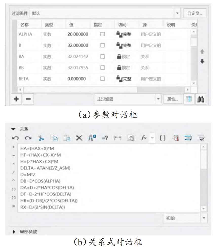
Firstly, in Creo Parametric 9.0 software, edit and define the parameter names and basic parameter values used in the modeling process in the dialog box shown in Figure 1 (a). Fill in the calculated parameter values as 0 and edit them one by one. Secondly, click on the icon “d=Relationship” and enter the basic relationship calculation formula for bevel gear in the dialog box, as shown in Figure 1 (b).
1.2.2 Drawing of involute of bevel gear
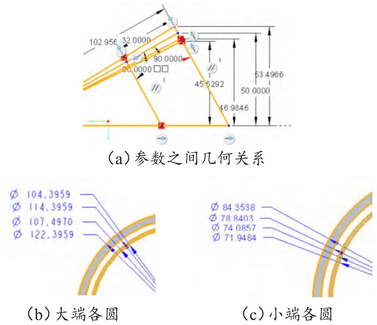
Create a new reference plane DTM1 on the TOP surface, with a distance of D0 and a value of “d/(2 * TAN (DELTA))”; Select both the LIGHT and FRONTT faces and create a new axis A_1; Select DTM1 and A_1 simultaneously to create a point PNT0. The sketch on LIGHT is shown in Figure 2 (a), with 102.956 3mm as the pitch and 32mm as the tooth width. The large and small back cone busbars have an angle of 90 ° with the split cone busbars, respectively. Establish a reference plane DTM2 based on the large back cone generatrix (passing through) and the LIGHT plane (normal), and establish a reference point PNT1 based on the large back cone generatrix and axis. On DTM2, with PNT1 as the center, draw the four circles at the large end as the tooth top circle Dza, the indexing circle Dz, the base circle Dzb, and the tooth root circle Dzf, as shown in Figure 2 (b). Similarly, the four circles at the small end are sequentially drawn as the tooth top circle Dza1, the indexing circle Dz1, the base circle Dzb1, and the tooth root circle Dzf1, as shown in Figure 2 (c).
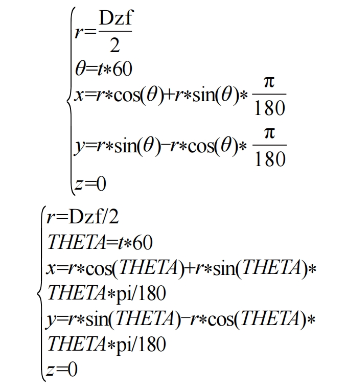
Draw the large end involute, i.e. curve 1, and sketch on the large end DTM2. Adjust the cone top to the appropriate angle of view, and sketch straight line 1 to connect the point and center at the 9 o’clock position on the left of the tooth root circle. Click on the tooth root circle to create axis A_2. Select point PNT1, create a new coordinate system CS0, with the large back cone generatrix as the X-axis, line 1 as the Y-axis, and A_2 as the Z-axis. Select CS0, click “Model Datum Coordinate System” in the menu bar, and in the pop-up coordinate system dialog box, rotate the direction around the Z-axis by 30 °. After clicking OK, a new coordinate system CS1 is created. Select CS1 and right-click to label the size. Use the “d=Relationship” tool, use the Relationship window, compare with the Z-axis, and add the relationship formula “D27=360 * COS (DELTA)/(4 * z)+180 * TAN (ALPHA)/PI ALPHA”. Click “Model – Regenerate”. Set the parameter t ∈ [0,1], add the following large end involute expression (1), model – reference (curve) – curve from equation – coordinate selection CS1, and the expression in Creo Parameter 9.0 is formula (2):
Move the involute of the bevel gear, use the “d=relationship” command, use the relationship window, add “$” and “- ()” to the left and right sides of “D27” in the above relationship, and regenerate again to obtain the involute of the first bevel gear at the large end. Offset the involute of the bevel gear by rotating “360 * COS (DELTA)/(4 * z)”. The bevel gear involute after mirror offset generates two involutes on the left and right sides of one tooth at the large end. Draw the small end involute, which is curve 2. The method of creating a small end involute is similar to that of a large end.
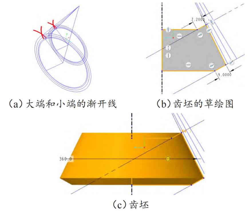
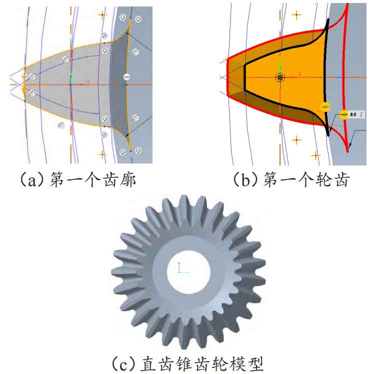
The small end involute equation is “r=Dzf1/2”, and the rest of the equation is the same as the large end involute equation. The involutes of the large and small ends are shown in Figure 3 (a), the sketch of the bevel gear blank is shown in Figure 3 (b), and the blank model is shown in Figure 3 (c).
1.3 Modeling of spur bevel gear
Using the “mixed scanning” command, select the tooth top circle, straight bevel gear tooth root circle, and two involutes that make up the large end section in sequence to project them. Use the trimming command to trim the projected lines to the style shown in Figure 4 (a), and fillet the transition between the two involutes and tooth root circles. After the large end section is drawn, use the same method to draw the small end section. A complete straight tooth can appear, as shown in Figure 4 (b). Copy and paste the teeth scanned above, with a rotation angle of 360 °/25=14.4 °, where 25 is the corresponding number of teeth. Then, perform an array operation on the previously copied teeth. The number of members in the array is Z-1, and the number of members in this instance is 24. At this point, the complete parameterized spur bevel gear can be obtained, as shown in Figure 4 (c).
1.4 Modeling of spiral bevel gear
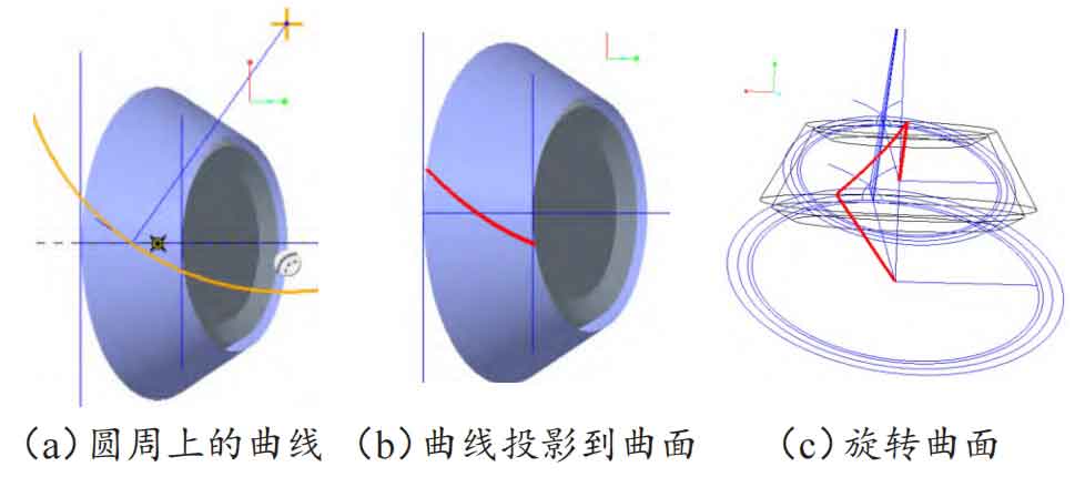
Modify the parameters at the rotation position of the spiral bevel gear blank as shown in Figure 5 (a) by adding two parameters, namely the midpoint helix angle β= 35 °, according to the calculation results in Table, the radius R of the cutterhead is 85.796 9 mm. Establish a reference plane DTM6 and place it: refer to the large back cone generatrix (passing through), and divide the cone generatrix (normal direction). Sketch on DTM6: Draw a horizontal line connecting the vertices of the large and small ends; Draw another straight line at the midpoint of the horizontal line at an angle of 35 ° to it; Draw another straight line at 125 ° to the horizontal line, with a length of R, and draw a circle with its endpoint as the center and length as the radius; Finally, based on the indexing busbar, rotate a indexing cone surface as shown in Figure 5 (a). Using the projection command, project the circle drawn above onto the indexing gear blank surface to obtain a projection curve, as shown in Figure 5 (b), which serves as the guide line for the involute section at both ends of the spiral bevel gear. Using the curve command through points, draw curves 3 and 4 respectively, connecting the guide line and the center of the large and small ends, as shown in Figure 5 (c).
| Code | Name | Parameter calculation value |
| d/mm | Dividing circle diameter | 100 |
| ha/mm | Tooth top height | 4 |
| δ/ (°) | Split cone angle | 29.054 6 |
| Rx/mm | Cone pitch | 102.956 3 |
| R/mm | Knife disc radius | 85.796 9 |
| θ A/(°) | Tooth tip angle | 2.224 9 |
| ba/mm | Tooth tip width | 32.024 1 |
| da/mm | Tooth tip circle diameter | 106.993 3 |
| hf/mm | Root height | 5 |
| θf/(°) | Root angle | 2.780 3 |
| bf/mm | Root width | 32.037 7 7 |
| df/mm | Root circle diameter | 91.258 4 |
| db/mm | Base circle diameter | 93.969 3 |
| hb/mm | Tooth base height | 3.449 5 |
| θb/(°) | Tooth base angle | 1.918 9 |
| bb/mm | Tooth base width | 32.018 0 |
| h/mm | Full tooth height | 9 |
| δa/(°) | Top cone angle | 31.279 5 |
| δf/(°) | Root cone angle | 27.135 7 |
| δb/(°) | Base cone angle | 27.135 7 |
| dzf/mm | Big end tooth root circle diameter | 104.395 9 |
| dzb/mm | Large end base circle diameter | 107.497 0 |
| dz/mm | Large end indexing circle diameter | 114.395 9 |
| dza/mm | Big end tooth tip circle diameter | 122.395 9 |
| dzf1/mm | Small end tooth root circle diameter | 71.948 4 |
| dzb1/mm | Small end base circle diameter | 74.085 7 |
| dz1/mm | Small end indexing circle diameter | 78.840 3 |
| dza1/mm | Small end tooth tip circle diameter | 84.353 8 |
| d1/mm | Top cone busbar length | 53.496 6 |
| d2/mm | Split cone busbar length | 50 |
| d3/mm | Base cone busbar length | 46.984 6 |
| d4/mm | Root cone busbar length | 45.629 2 |
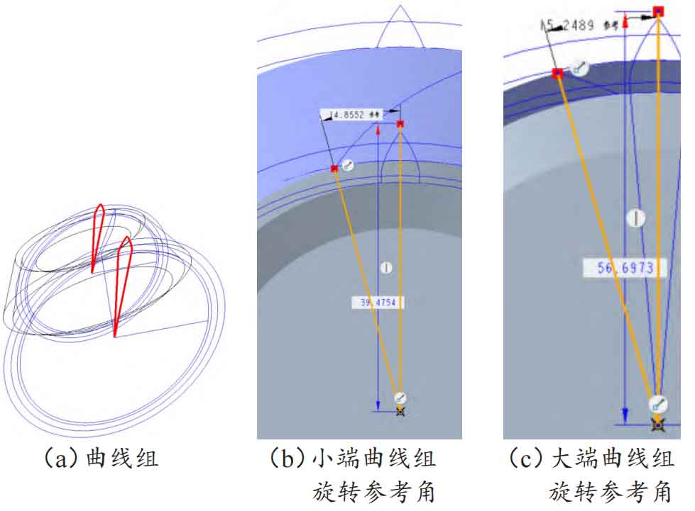
Draw a group of involute curves. Using the point curve command, draw the curve, use the trim command, first trim off the excess involutes at the large and small ends, and then connect the involutes at the large and small ends and the center of the circle at the large and small ends respectively. The connected result is shown in Figure 6 (a). On the small circular surface of the gear blank, draw the angle at which the small end curve group needs to rotate and mark it as the reference dimension for the small end, as shown in Figure 6 (b). Similarly, on the large circular surface of the gear blank, sketch the angle at which the large end involute needs to rotate and mark it as the reference dimension for the large end, as shown in Figure 6 (c).
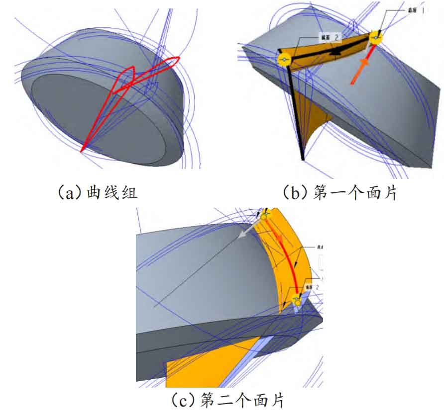
First move the involute group at the large end, select the trimmed curve group at the large end in sequence, and use the command “Copy Paste (Selective Paste)”. After the “Move (Copy)” dialog box pops up, select the type of rotation, refer to the center axis of the selected tooth blank, and fill in the “offset” with the large end rotation angle referenced above. Move the involute group of the small end again, and fill in the “offset” with the small end rotation angle referenced above. The final rotation result is shown in Figure 7 (a). Use “scan blending” to connect the surface patches on one side of the large end involute group and the other side of the small end involute group, as shown in Figure 7 (b). Using the same method, scan and mix the surface group at the other end, and the final result of merging the two surfaces is shown in Figure 7 (c).
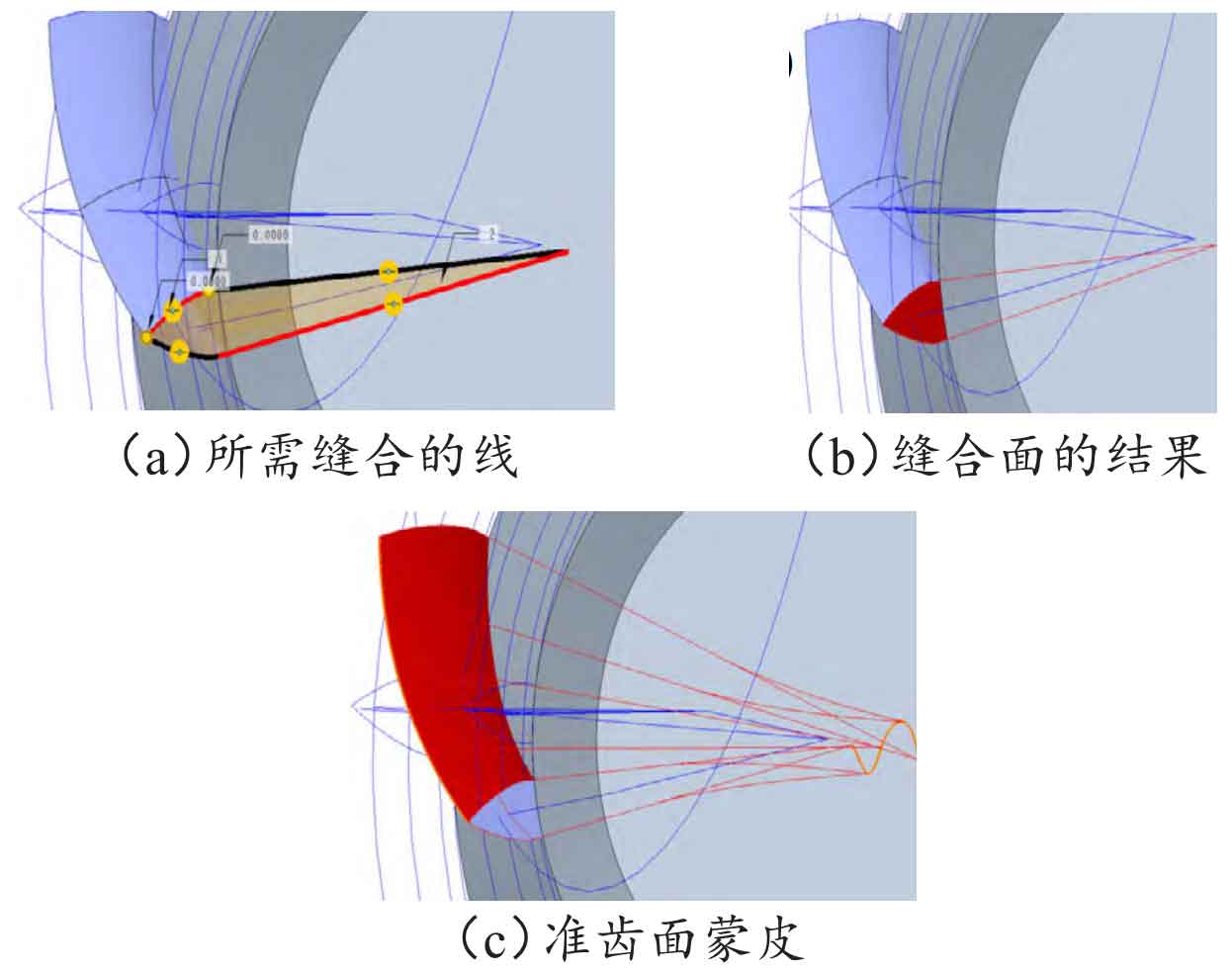
Using boundary blending to stitch the curves at the large and small ends. First, stitch the curve at the small end, select the four thick lines with dots in Figure 8 (a), and the final stitching result is shown in Figure 8 (b). Suture the curve at the large end using the same method as the small end. Then perform boundary blending on the two scanned and mixed surface patches, use the merge command, select the two surface patches by reference and confirm, and merge the quasi tooth surface skin as shown in Figure 8 (c).
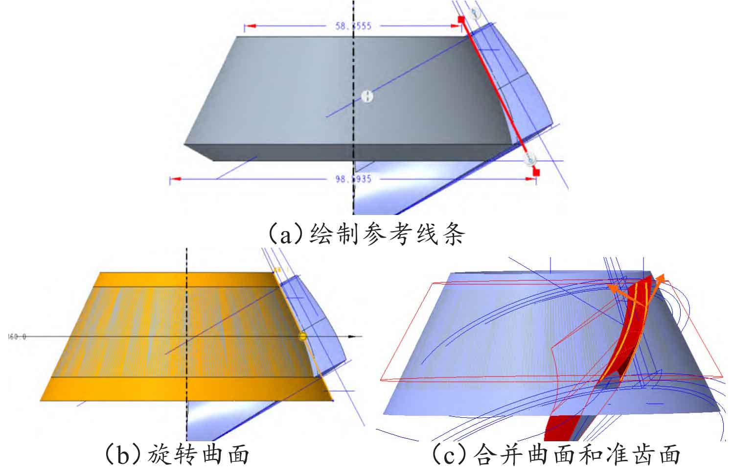
Perform a fusion operation between the surface group above and the tooth blank entity. Draw a straight line using the generatrix of the root cone as a reference, as shown in Figure 9 (a). Use the “Rotate” command, select “Surface” as the type, select the rotation center of the gear blank as the axis, and the rotated surface is shown in Figure 9 (b); Merge the rotated surfaces and surface groups, as shown in Figure 9 (c).
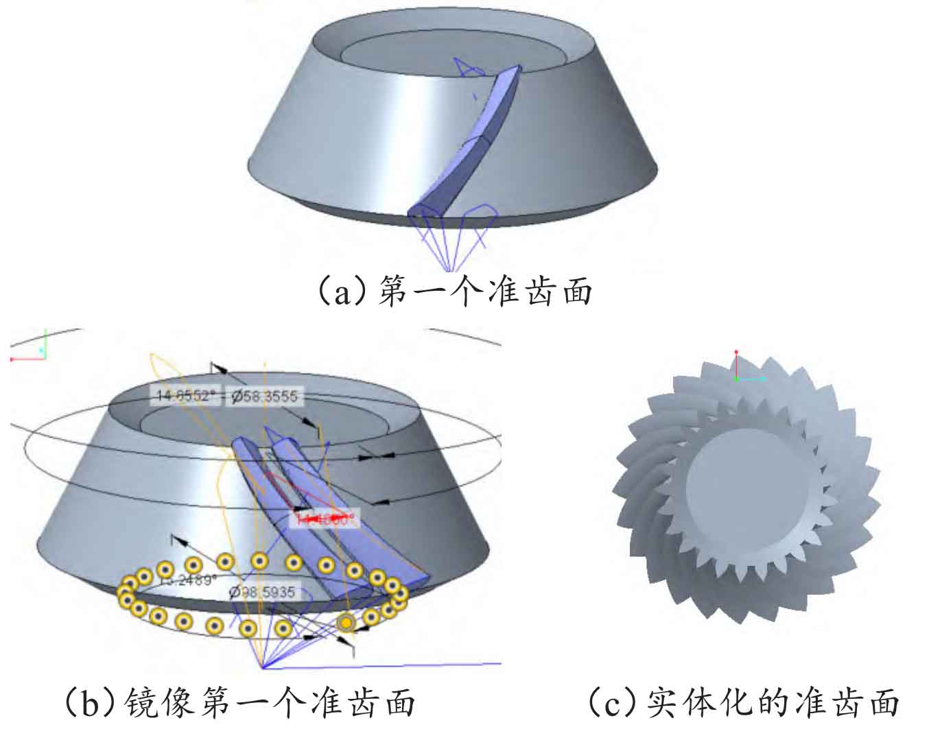
The final merged result of the first bevel gear quasi tooth surface is shown in Figure 10 (a). Merge the steps above to obtain the first quasi tooth surface into a group in the project tree, and mirror the group. The result is shown in Figure 10 (b), with the aim of converting the bevel gear tooth surface into left-hand rotation. Hide the first quasi tooth surface, keep the mirrored quasi tooth surface, and perform “Copy Paste (Selective Paste) Apply Move/Rotate Transform to Copy”. In the pop-up “Copy (Move)” dialog box, select “Axis” and click on the axis of the gear blank. After calculation, the rotation angle is 14.4 °. Array the copied quasi tooth surface, set the axis of the first direction to select the tooth blank, and select Z-1 members. In this case, it is 24. Due to the fact that the quasi tooth surface at this time is only a curved surface rather than a solid, it is necessary to solidize the quasi tooth surface of the bevel gear. Select the quasi tooth surface group that was just mirrored, click “Solid”, and select “Fill Solid” as the type in the pop-up dialog box. At this point, the mirrored bevel gear quasi tooth surface group becomes a solid model. Perform the same solid operation on the second adjacent quasi tooth surface group, and array the results of the second solid operation. After completing the entire circle of 25 bevel gear quasi tooth surface groups, they all become solid, as shown in Figure 10 (c).
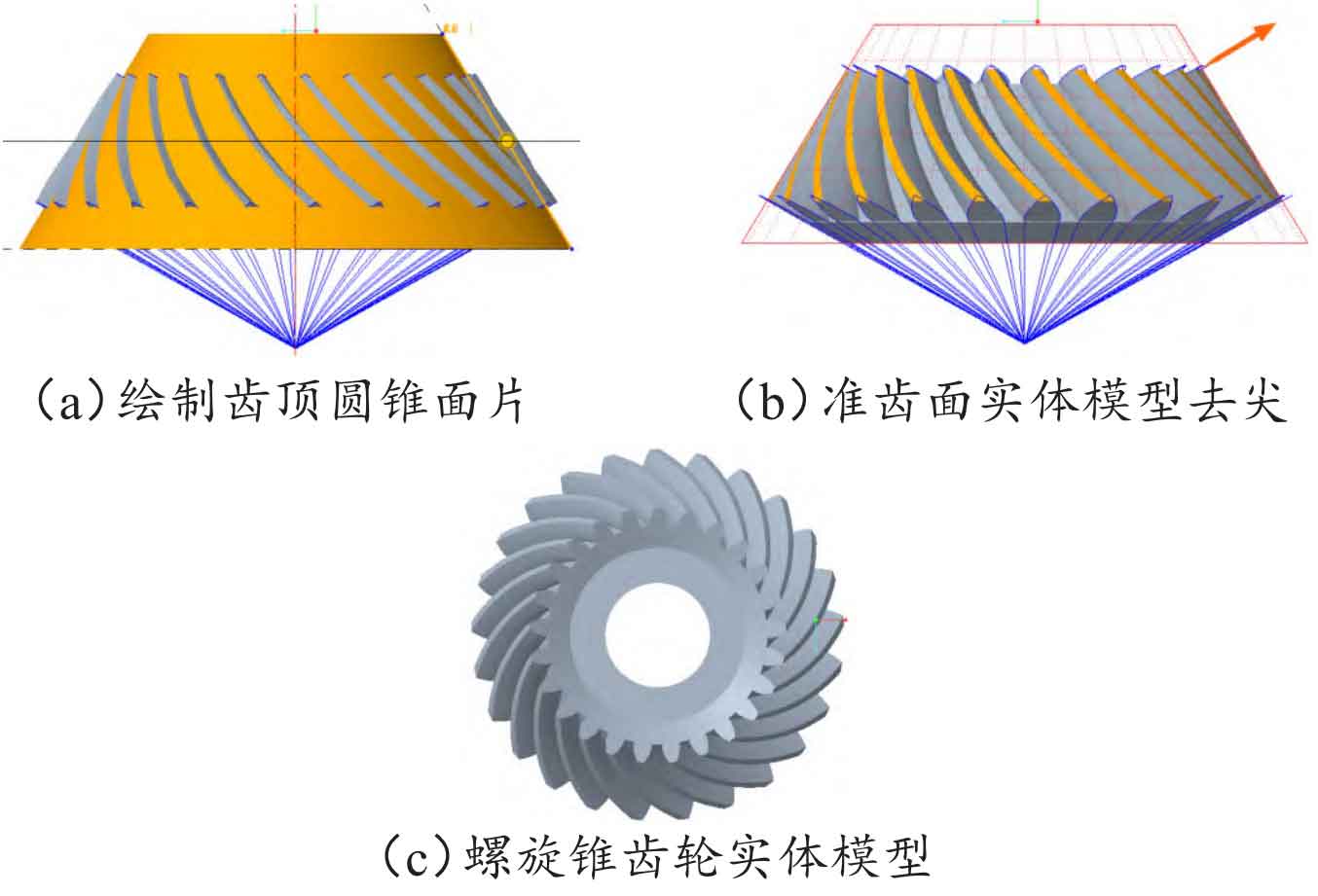
The spiral bevel gear used in production applications does not have the outer part of the yellow tooth tip conical surface in Figure 11 (a), so it needs to be removed. Using the “Rotate” command, draw a surface with the generatrix of the top cone as a reference. The result after using the “Remove Material” command is shown in Figure 11 (b). After determining, draw a through circular hole with a diameter of 30mm in the middle of the spiral bevel gear model, and finally obtain the solid model of the spiral bevel gear as shown in Figure 11 (c).
2. 3D printing of bevel gear
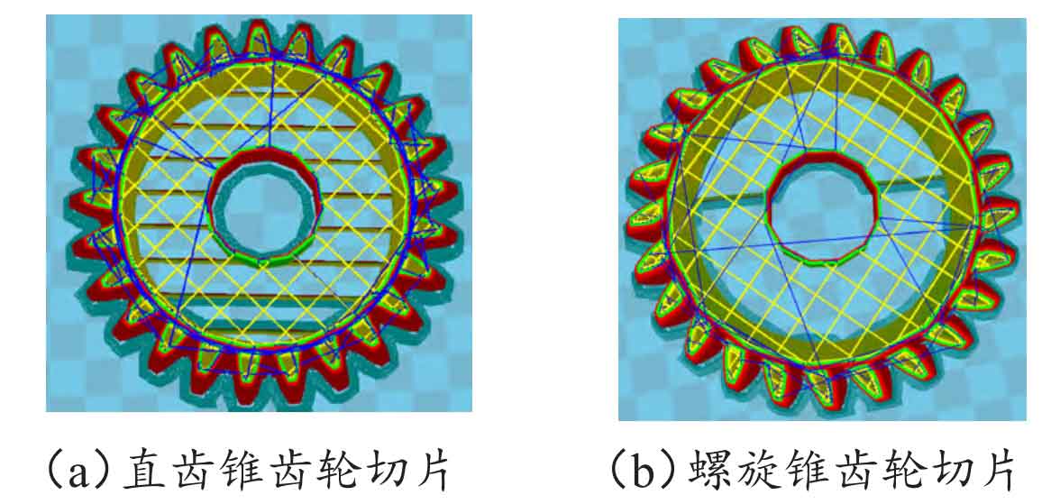
Output the parameterized bevel gear modeled in the previous text to STL format in C r e o Parametric 9.0, and slice the model in slicing software. Figure 12 (a) shows the slicing processing of the straight bevel gear model, and Figure 12 (b) shows the slicing processing of the spiral bevel gear model.
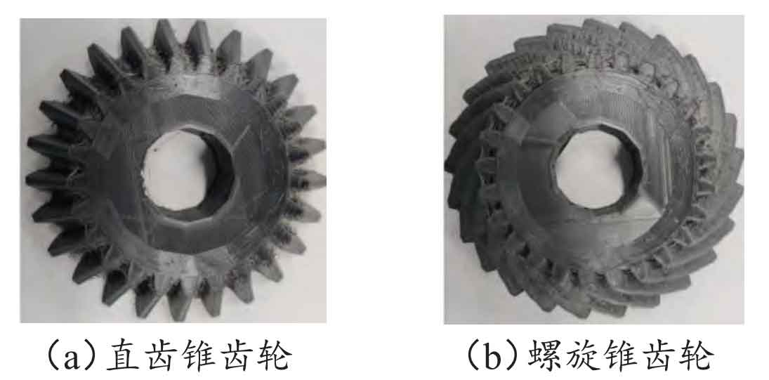
The key parameter settings before 3D printing are: layer height 0.2 mm, wall thickness 1.2 mm; The thickness of the bottom and top layers is 1.0 mm, with a filling density of 10%; Printing speed of 40 mm/s, nozzle temperature of 210 ℃, hot bed temperature of 40 ℃; The support type is local support, and the platform attachment type is the bottom edge line; The printing material is PLA, with a diameter of 1.75 mm and an extrusion rate of 100%; The diameter of the machine nozzle is 0.4 mm, the rewinding speed is 40 mm/s, and the rewinding length is 4 mm; The initial layer thickness is 0.2 mm, the initial layer line width is 100%, the bottom layer is not cut off, and the overlap between two extrudations is 0.15 mm; The movement speed, bottom printing speed, fill printing speed, top and bottom printing speed, outer wall printing speed, and inner wall printing speed are all set to 40 mm/s; Cooling each layer for a minimum printing time of 5 seconds, turn on the fan for cooling. The printing entity of spur bevel gear is shown in Figure 13 (a), and the printing entity of spiral bevel gear is shown in Figure 13 (b).
3. Conclusion
ZHY Gear has developed a program using MATLAB software to derive the calculation parameters of bevel gear, greatly reducing the workload of manual calculations and making formula derivation fast and accurate. The parametric modeling of spur bevel gear and helical bevel gear is similar, with the difference being the final tooth profile construction. By studying and analyzing the important steps in the modeling process of bevel gear, the parameterization method is adopted to model bevel gear, which greatly reduces the difficulty of modeling. Since only changing the basic parameters can obtain the corresponding new model, this method has the characteristics of being fast, efficient, and accurate, providing new ideas for the modeling of bevel gear. Combined with 3D printing technology, compared to traditional CNC machine tools, it can obtain the actual model more quickly, saving a lot of manpower and financial resources, and has significant practical significance.