
The pursuit of high precision and surface finish in the manufacturing of spiral bevel gears places stringent demands on the stability of the machining process. A critical challenge encountered during gear milling operations on specialized machine tools is the phenomenon of chatter—a self-excited vibration that severely deteriorates workpiece quality, increases tool wear, and limits productivity. The origin of this instability is often deeply rooted in the dynamic characteristics of the machine tool’s structural components, with the tool spindle system being a primary contributor. The spindle-bearing assembly, transmitting power and motion to the cutting tool, acts as the final mechanical link in the force loop. Its dynamic compliance directly influences the system’s susceptibility to regenerative chatter. Therefore, developing a high-fidelity, computationally efficient dynamic model for the spindle system of a gear milling machine is paramount for predictive analysis, performance optimization, and ultimately, for enabling stable, high-quality machining of complex spiral bevel gears.
The core of the dynamic analysis lies in accurately representing the rotating spindle and its supporting bearings. For the spindle rotor, which operates at relatively low speeds in heavy-duty gear milling applications, the Timoshenko beam theory provides an excellent foundation. This theory accounts for both shear deformation and rotary inertia, effects which become significant for short, stout spindles typical in such machines, unlike the Euler-Bernoulli beam which neglects them. The continuous spindle is discretized using the lumped mass method, where distributed mass and stiffness properties are concentrated at specific nodes along the shaft, significantly simplifying the equations of motion while retaining essential dynamic features. The kinetic and potential energy of the system are formulated, and via Lagrange’s equations, the undamped matrix equation of motion is derived:
$$ \mathbf{M} \ddot{\mathbf{X}} + \mathbf{K} \mathbf{X} = \mathbf{F}(t) $$
where \(\mathbf{M}\) is the mass matrix, \(\mathbf{K}\) is the stiffness matrix, \(\mathbf{X}\) is the displacement vector, and \(\mathbf{F}(t)\) is the force vector containing static (e.g., gravity) and dynamic (e.g., unbalance) loads. Solving the eigenvalue problem \( |\mathbf{K} – \omega_n^2 \mathbf{M}| = 0 \) yields the system’s natural frequencies \(\omega_n\), which are critical for avoiding resonance.
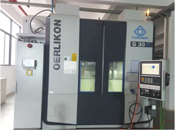
The stiffness matrix \(\mathbf{K}\) is assembled from the contributions of the shaft and the bearings. For the Timoshenko beam element connecting two nodes, the relationship between forces/moments and displacements/rotations at its ends can be expressed through a dynamic stiffness matrix or its static counterpart for low-frequency analysis. This matrix incorporates the geometry, material properties (Young’s modulus \(E\), shear modulus \(G\)), and shear correction factors. The bearing stiffness, however, presents a more complex, nonlinear challenge. In a gear milling spindle, tapered roller bearings are frequently employed due to their high load capacity and rigidity. Their stiffness is not constant but depends on the internal preload and the external operational loads.
The modeling of tapered roller bearings requires a detailed contact mechanics approach. Under an axial preload \(F_{a0}\), essential for eliminating internal clearance and enhancing rigidity, each roller develops a contact force. The resultant axial stiffness \(k_a\) of the bearing can be derived from Hertzian contact theory and is a function of the preload, number of rollers \(Z\), contact angle \(\alpha\), and effective roller length \(l_a\). A simplified expression for the axial displacement \(\delta_a\) under preload is:
$$ \delta_a = \frac{6 \times 10^{-4}}{\sin \alpha} Q^{0.9} l_a^{0.8} \quad \text{with} \quad Q = \frac{F_{a0}}{Z \sin \alpha} $$
The axial stiffness is then \(k_a = F_{a0} / \delta_a\). The radial stiffness \(k_r\) is equally crucial as it governs the spindle’s response to radial cutting forces during gear milling. It is influenced by both the axial preload (which generates a radial component \(F_{ar} = F_{a0} \sin \alpha\)) and the external radial load \(F_{or}\). Its nonlinear nature is often approximated by a secant stiffness or a linearized stiffness around the operating point, which can be estimated as:
$$ k_r \approx \frac{\Delta F_r}{\Delta \delta_r} $$
where \(\Delta F_r\) is a small change in total radial load (\(F_r = F_{ar} + F_{or}\)) and \(\Delta \delta_r\) is the corresponding radial deflection. Accurate calculation often requires iterative methods to solve the system of equations governing the load distribution among all rollers.
The following table summarizes the key modeling approaches for the major components in a gear milling spindle dynamic analysis:
| System Component | Modeling Method | Key Parameters/Equations | Purpose in Dynamic Model |
|---|---|---|---|
| Spindle Rotor | Timoshenko Beam Theory with Lumped Mass Discretization | $$ \mathbf{M}_r, \mathbf{K}_r $$ from energy methods/Lagrange. $$ \rho, E, G, A, I, k $$. | Captures flexural and shear deformation. Provides mass and stiffness matrices for the shaft. |
| Tapered Roller Bearings | Nonlinear Contact Stiffness Model (Hertzian) | Axial: \(k_a = f(F_{a0}, Z, \alpha, l_a)\). Radial: \(k_r = f(F_{a0}, F_{or}, \alpha, \text{geometry})\). | Provides boundary condition stiffnesses. Major source of nonlinearity and damping (not modeled here). |
| Tool & Accessories (Flange, Motor Rotor) | Lumped Mass and Inertia | Mass \(m_d\), Diametral Inertia \(J_d\), Gyroscopic Matrix \(\mathbf{G}\). | Adds significant mass and inertia. Gyroscopic effects can split critical speeds. |
| Complete Spindle System | Finite Element or Transfer Matrix Method | Assembly: $$ \mathbf{M}_\text{sys} = \sum \mathbf{M}_i, \quad \mathbf{K}_\text{sys} = \sum \mathbf{K}_i + \mathbf{K}_\text{bearing} $$. | Forms the global system matrices for eigenvalue (modal) and forced response analysis. |
Once the model is established, numerical analysis is performed to extract its dynamic characteristics. For the gear milling spindle under study, the first several natural frequencies and mode shapes are calculated. To validate the accuracy of this physics-based model, experimental modal analysis is indispensable. A common approach is the impact hammer test, where the spindle housing (or a non-rotating spindle) is tapped with a force hammer equipped with a load cell. The response is measured at several locations using accelerometers. By processing the input force and output acceleration signals, the Frequency Response Functions (FRFs) are obtained, from which the experimental natural frequencies and damping ratios can be extracted.
A comparison between the numerical predictions and experimental results is the ultimate validation. The table below illustrates a typical comparison for the first five modal frequencies of a gear milling spindle:
| Mode Order | Experimental Frequency (Hz) | Numerical Frequency (Hz) | Relative Error (%) | Description of Mode Shape |
|---|---|---|---|---|
| 1 | 880.4 | 1002.5 | +13.9 | First Bending (in XY plane) |
| 2 | 1805.6 | 1985.2 | +9.9 | First Bending (in XZ plane, orthogonal to Mode 1) |
| 3 | 2568.1 | 2769.4 | +7.8 | Second Bending |
| 4 | 2801.9 | 2980.5 | +6.4 | First Torsional / Mixed Mode |
| 5 | 2883.3 | 3009.1 | +4.4 | Coupled Bending-Axial Mode |
The consistent overestimation of frequencies by the numerical model is typical and can be attributed primarily to the omission of damping and the idealization of boundary conditions (e.g., assuming perfectly rigid housing foundations). In reality, joints, interfaces, and material damping absorb energy and generally lower the system’s natural frequencies. Despite these simplifications, the model demonstrates excellent correlation in terms of frequency ranking and relative spacing, proving its effectiveness in capturing the essential dynamics of the gear milling spindle. This validated model becomes a powerful digital twin.
With a validated model, engineers can perform virtual experiments to optimize the spindle’s design for enhanced chatter resistance in gear milling. Key parameters can be systematically varied to observe their impact on the dynamic stiffness, which is the inverse of the frequency response function magnitude at the tool point. A primary target for optimization is the bearing preload. As the analysis shows, increasing the axial preload from a nominal value to a higher, yet safe, operational level significantly raises the first few natural frequencies:
$$ \text{For } F_{a0,\text{nominal}} \rightarrow F_{a0,\text{high}}: \quad f_{n1} \uparrow \text{ by } \approx 30\%,\quad f_{n2} \uparrow \text{ slightly},\quad f_{n3} \uparrow \text{ slightly} $$
This upward shift in natural frequencies is often desirable as it can move critical speeds away from the operational speed range of the gear milling process and increase the minimum stability limit, effectively enlarging the “stable valley” in the stability lobe diagram. Other optimization studies can involve:
1. Bearing Configuration: Analyzing the effect of bearing spacing (\(L\) in the model). An optimal spacing exists that maximizes the first natural frequency, balancing the shaft’s bending stiffness against the bearings’ support stiffness.
2. Shaft Geometry: Modifying diameters, overhang lengths, and introducing damping rings or inertia disks to tailor the mode shapes and frequencies.
3. Material Selection: Using materials with higher specific stiffness (\(E/\rho\)) or incorporating composite structures.
The final and most critical application is in predicting and avoiding chatter. By coupling the spindle dynamic model (represented by its Tool Point Frequency Response Function \(\mathbf{G}(i\omega)\)) with a model of the cutting process (represented by the specific cutting force coefficients and the immersion-dependent directional factors), the stability of the gear milling operation can be predicted. The well-known stability limit for a single-mode system is given by:
$$ a_{\lim} = -\frac{2 \pi \Lambda_R}{K_f N} \left(1 + \kappa^2\right) $$
where \(a_{\lim}\) is the critical depth of cut, \(\Lambda_R\) is the real part of the eigenvalue of the dynamic system, \(K_f\) is the specific cutting force coefficient, \(N\) is the number of teeth, and \(\kappa\) is a ratio related to the system’s frequency and the tooth passing frequency. For multi-mode systems, the stability lobe diagram is constructed numerically. The validated spindle model provides the accurate \(\mathbf{G}(i\omega)\) needed for this calculation, allowing process planners to select spindle speeds and depths of cut that lie within stable regions, thereby eliminating chatter before the first physical cut is made in a gear milling operation.
In conclusion, the development and validation of a comprehensive dynamic model for the spindle-bearing system in a spiral bevel gear milling machine is a fundamental engineering task with direct implications for manufacturing quality and efficiency. By employing the lumped mass method for discretization, Timoshenko beam theory for the rotor, and nonlinear stiffness models for tapered roller bearings, a high-fidelity yet computationally manageable model can be constructed. Experimental modal analysis serves as a crucial step for validating and tuning this model. Once validated, the model transcends being merely a descriptive tool and becomes a predictive and prescriptive asset. It enables the virtual optimization of spindle design parameters—most notably bearing preload—for increased dynamic stiffness and higher natural frequencies. Ultimately, this model forms the backbone for stability prediction, empowering manufacturers to plan chatter-free gear milling processes, ensuring the production of high-precision, quiet, and durable spiral bevel gears with exceptional surface integrity. This integrated approach from modeling to validation to application represents the modern paradigm for achieving stability and precision in advanced manufacturing processes like spiral bevel gear milling.