
The pursuit of higher precision, speed, and reliability in industrial robotics has placed unprecedented demands on their core components. Among these, the rotary vector reducer stands as a critical transmission element within robotic joints, renowned for its compact size, high reduction ratio, and excellent torsional stiffness. The operational health of the rotary vector reducer directly dictates the positioning accuracy, efficiency, and long-term reliability of the entire robotic system. Consequently, developing robust and effective fault diagnosis methodologies for these precision reducers is of paramount importance for predictive maintenance and minimizing downtime.
Monitoring robotic joint health typically relies on signals such as vibration, acoustics, or current. While vibration signals are highly sensitive to incipient mechanical faults like gear cracks, their interpretation in a robotic context is complicated by the joint’s inherent non-stationary, reciprocating motion patterns. Directly extracting stable rotational speed information for fault frequency calculation from vibration data alone is often impractical. Conversely, the servo motor current signal, which is relatively easy to acquire and less susceptible to external mechanical noise, provides a direct reflection of the motor’s operational state and, by extension, the torque and speed of the connected rotary vector reducer’s input stage. Therefore, a synergistic approach that fuses the high-fidelity fault information from vibration signals with the reliable rotational speed estimation from current signals presents a powerful and practical solution for diagnosing faults within the sealed environment of a robotic joint.
This article addresses the specific challenge of diagnosing planet gear root cracks in rotary vector reducers—a fault that manifests subtly during operation and is difficult to isolate due to the reducer’s complex frequency spectrum with multiple interacting components. We propose a novel fault identification method that integrates servo motor current analysis, envelope demodulation, information entropy, and Variational Mode Decomposition (VMD). The core innovation lies in using the current signal to accurately estimate the input sun gear rotational frequency during stable operation, synchronously segment the corresponding vibration data, and then apply advanced signal processing techniques to extract the weak, fault-induced modulations from the complex vibration signature.
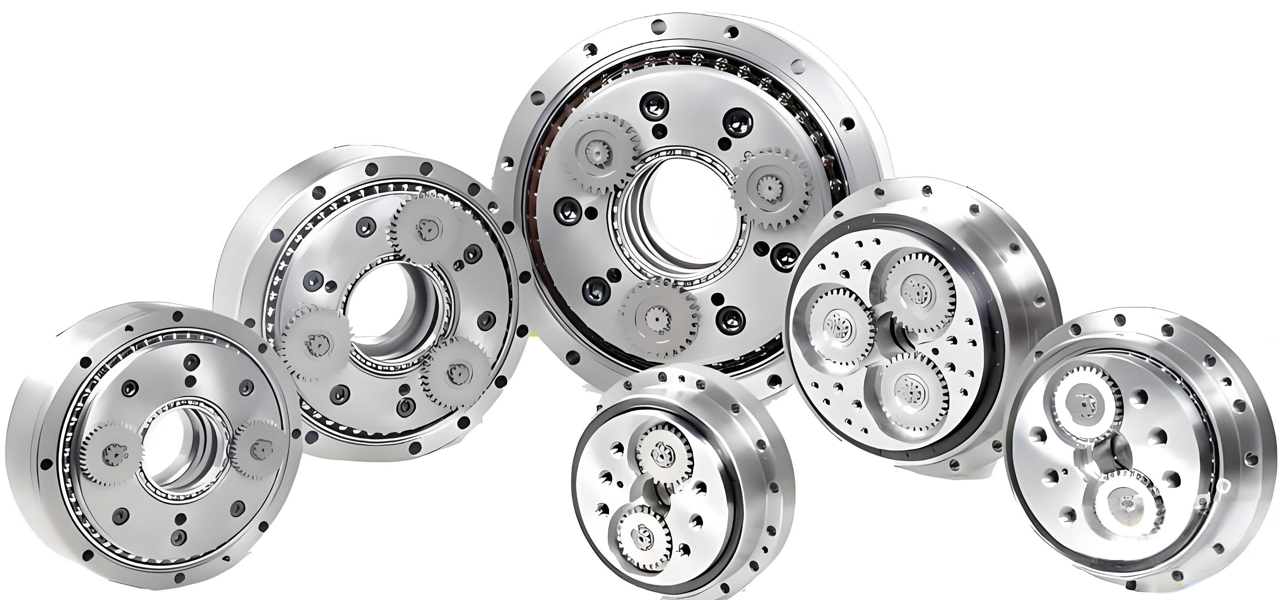
The diagnostic framework for the rotary vector reducer is systematic. First, the servo motor current signal is analyzed to obtain the instantaneous frequency trend. The stable operational phase is identified from this trend, and the sun gear rotation frequency ($f_s$) is calculated from the dominant spectral component in this phase. This frequency serves as the fundamental reference for computing all subsequent theoretical characteristic frequencies of the rotary vector reducer, such as the planet gear rotational frequency and the first-stage meshing frequency.
Simultaneously, based on the time indices from the current signal’s stable phase, the corresponding segment of the vibration signal is extracted. This ensures the analysis focuses on data from a quasi-constant speed period, avoiding the complicating effects of acceleration and deceleration. An initial envelope analysis of this vibration segment is performed to identify frequency bands where potential fault-related amplitude modulations are present, providing a target range for finer analysis.
The heart of the feature extraction lies in processing this vibration segment. Given the dense frequency spectrum of a healthy rotary vector reducer, the fault-induced features are often masked. To isolate them, the vibration signal is decomposed using Variational Mode Decomposition (VMD). VMD adaptively decomposes a signal into a discrete number of band-limited Intrinsic Mode Functions (IMFs). To automatically select the IMF most relevant to the planet gear fault, the concept of information entropy is employed. The signal is divided into blocks based on the calculated fault period, and the entropy of each IMF is computed. The IMF with an entropy value closest to that of the original signal (indicating it carries the primary ordered, fault-related impulse components) is selected for final spectral analysis. The flowchart below summarizes this integrated diagnostic process for the rotary vector reducer.
| Step | Signal | Action | Purpose/Output |
|---|---|---|---|
| 1 | Current | Spectrum & Instantaneous Frequency Analysis | Estimate stable-phase sun gear rotation frequency ($f_s$). |
| 2 | – | Theoretical Calculation | Compute reducer characteristic frequencies (e.g., meshing frequency $f_m$, planet gear frequency $f_p$). |
| 3 | Vibration | Synchronous Segmentation | Extract vibration data corresponding to the current signal’s stable phase. |
| 4 | Vibration | Envelope Demodulation | Identify candidate frequency bands containing fault modulations. |
| 5 | Vibration | VMD Decomposition | Separate signal into K band-limited IMF components. |
| 6 | IMF Components | Information Entropy Selection | Select the optimal IMF carrying fault features. |
| 7 | Optimal IMF | Spectral & Envelope Analysis | Identify and validate fault characteristic frequencies ($f_{fault}$). |
Theoretical Foundation: VMD and Information Entropy
Variational Mode Decomposition (VMD): VMD is a fully non-recursive, adaptive signal decomposition technique. It aims to decompose a real-valued input signal $x(t)$ into a predefined number $K$ of discrete sub-signals or modes $u_k(t)$, each having a specific sparsity property in the spectral domain. Essentially, each mode $u_k(t)$ is compact around a central pulsation $\omega_k$, which is determined along with the decomposition.
The algorithm constructs and solves a constrained variational problem. The goal is to minimize the sum of the estimated bandwidths of all modes, ensuring that the sum of all modes reconstructs the original signal. The constrained variational problem is formulated as follows:
$$
\min_{\{u_k\},\{\omega_k\}} \left\{ \sum_{k=1}^K \left\| \partial_t \left[ \left( \delta(t) + \frac{j}{\pi t} \right) * u_k(t) \right] e^{-j\omega_k t} \right\|_2^2 \right\}
$$
$$
\text{subject to} \quad \sum_{k=1}^{K} u_k = x(t)
$$
Here, $\{u_k\} = \{u_1, …, u_K\}$ and $\{\omega_k\} = \{\omega_1, …, \omega_K\}$ are the sets of all modes and their center frequencies, respectively. $\partial_t$ denotes the partial derivative with respect to time, $\delta(t)$ is the Dirac delta distribution, $j$ is the imaginary unit, and $*$ represents convolution.
To render the problem unconstrained, a quadratic penalty term and Lagrangian multipliers $\lambda$ are introduced, leading to the Augmented Lagrangian $\mathcal{L}$:
$$
\begin{aligned}
\mathcal{L}(\{u_k\},\{\omega_k\},\lambda) &= \alpha \sum_{k} \left\| \partial_t \left[ \left( \delta(t) + \frac{j}{\pi t} \right) * u_k(t) \right] e^{-j\omega_k t} \right\|_2^2 \\
&+ \left\| x(t) – \sum_{k} u_k(t) \right\|_2^2 + \left\langle \lambda(t), x(t) – \sum_{k} u_k(t) \right\rangle
\end{aligned}
$$
The parameter $\alpha$ is the penalty factor that balances the data fidelity constraint. This Lagrangian is then solved using the Alternate Direction Method of Multipliers (ADMM), which iteratively updates $u_k^{n+1}$, $\omega_k^{n+1}$, and $\lambda^{n+1}$ in the frequency domain:
$$
\hat{u}_k^{n+1}(\omega) = \frac{\hat{x}(\omega) – \sum_{i \ne k} \hat{u}_i(\omega) + \frac{\hat{\lambda}(\omega)}{2}}{1 + 2\alpha (\omega – \omega_k^n)^2}
$$
$$
\omega_k^{n+1} = \frac{\int_0^\infty \omega |\hat{u}_k^{n+1}(\omega)|^2 d\omega}{\int_0^\infty |\hat{u}_k^{n+1}(\omega)|^2 d\omega}
$$
The update for the Lagrangian multiplier is:
$$
\hat{\lambda}^{n+1}(\omega) = \hat{\lambda}^{n}(\omega) + \tau \left( \hat{x}(\omega) – \sum_{k=1}^{K} \hat{u}_k^{n+1}(\omega) \right)
$$
The iteration continues until convergence, satisfying the condition: $\sum_{k} \| u_k^{n+1} – u_k^{n} \|_2^2 / \| u_k^{n} \|_2^2 < \epsilon$. For the diagnosis of the rotary vector reducer, VMD’s ability to clearly separate closely spaced frequency components in a dense spectrum is crucial for isolating fault-related sidebands.
Information Entropy: Information entropy is a measure of the uncertainty or randomness in a signal or system. For a discrete random variable $X$ with possible outcomes $\{x_1, x_2, …, x_n\}$ and corresponding probabilities $p(x_i)$, the Shannon entropy $H(X)$ is defined as:
$$
H(X) = -\sum_{i=1}^{n} p(x_i) \log_2 p(x_i)
$$
A higher entropy value indicates greater unpredictability or disorder, while a lower value suggests more order or regularity. In the context of fault diagnosis for a rotary vector reducer, the appearance of a periodic fault impulse (like a gear crack) injects a degree of order into the vibration signal. Consequently, the IMF component that predominantly carries this periodic fault information will typically exhibit a lower information entropy compared to components containing noise or other unrelated vibrations. By calculating the entropy of each IMF obtained from VMD and comparing it to the entropy of the original signal, the component that best represents the ordered fault signature can be automatically selected for detailed spectral analysis.
Fault Characteristic Frequencies of the Rotary Vector Reducer
The rotary vector reducer features a two-stage reduction mechanism. The first stage is a standard planetary gear train, and the second stage is a cycloidal pinwheel mechanism. Accurate calculation of characteristic frequencies is essential for fault identification. The sun gear, connected to the servo motor, is the input.
Let the sun gear rotational speed be $n_s$ (RPM). The fundamental rotational frequency of the sun gear ($f_s$) is:
$$
f_s = \frac{n_s}{60} \quad \text{(Hz)}
$$
For a rotary vector reducer with a fixed pinwheel, the meshing frequency of the first-stage planetary gear train ($f_m$) and the rotational frequency of the planet gear relative to the carrier ($f_p$) are given by:
$$
f_m = \frac{Z_s Z_p}{Z_s + Z_p} \cdot f_s
$$
$$
f_p = \frac{Z_s Z_c}{(Z_c – Z_p)(Z_s + Z_p)} \cdot f_s
$$
where $Z_s$, $Z_p$, and $Z_c$ are the tooth numbers of the sun gear, planet gear, and cycloid disc, respectively. (Note: These are simplified forms; the exact kinematics consider the unique configuration of the RV transmission).
When a root crack develops on a planet gear in the rotary vector reducer, it generates a periodic impulsive force each time the cracked tooth meshes with the sun gear. This impulse amplitude-modulates the regular meshing vibration. In the frequency domain, this manifests as sidebands spaced at the planet gear’s fault characteristic frequency around the meshing frequency ($f_m$) and its harmonics. The primary fault characteristic frequency ($f_{f1}$) is typically the planet gear’s rotational frequency relative to the carrier ($f_p$) or the sun gear’s rotational frequency ($f_s$), depending on the sensor location and dynamics. Sidebands appear at $f_m \pm n \cdot f_{f1}$. A secondary set of modulation sidebands at $f_m \pm n \cdot (f_{f1} + f_{f2})$ may also emerge due to the combined effect of the crack and the planet gear’s revolution, where $f_{f2}$ is another relevant rotational frequency.
| Fault Type | Spectral Manifestation | Description |
|---|---|---|
| Planet Gear Root Crack | Increased amplitude at $f_m$ and harmonics. | The impulsive impact excites the meshing frequency. |
| Appearance of sidebands at $f_m \pm n \cdot f_{f1}$. | Amplitude modulation caused by the periodic fault impulse. The sideband amplitude may rival or exceed that of the meshing frequency. |
Experimental Analysis and Diagnosis Procedure
The proposed methodology was validated using a test bench designed to simulate a robotic joint’s reciprocating motion. The setup included a rotary vector reducer (RV-40E type, reduction ratio 121) with an artificially induced root crack on one of its two planet gears. A servo motor drove the system. Data acquisition involved a clamp-on current transformer on the motor driver’s U-phase output (sampling frequency: 25.6 kHz) and a uniaxial accelerometer mounted on the servo motor housing (sampling frequency: 1 MHz). The joint performed an 80-degree lift-and-hold motion.
| Component | Symbol | Number of Teeth |
|---|---|---|
| Sun Gear | $Z_s$ | 12 |
| Planet Gear | $Z_p$ | 42 |
| Cycloid Disc | $Z_c$ | 39 |
| Needle Gear | $Z_n$ | 40 |
Step 1: Current-based Speed Estimation and Synchronization. The current signal was processed to obtain its instantaneous frequency trend via the Hilbert Transform. The stable operational phase (approximately 1-2 seconds into the motion) was identified. The spectrum of the current signal in this phase showed a dominant peak at 62.7 Hz, corresponding to the electrical frequency. For a servo motor with $P$ pole pairs, the mechanical speed $n_s$ is given by $n_s = 60 \cdot f_e / P$. With $P=5$, the estimated sun gear speed was $n_s = 752.4$ RPM, yielding $f_s = 12.54$ Hz. This stable-phase time window was then used to synchronously extract the corresponding segment of the raw vibration signal from the rotary vector reducer for analysis.
Step 2: Theoretical Frequency Calculation and Initial Vibration Assessment. Using $f_s$, the key theoretical frequencies for the rotary vector reducer were calculated as shown in the table below. An initial envelope analysis of the segmented vibration signal was performed. Compared to a healthy baseline, the envelope spectrum of the faulty signal showed a significant elevation in the amplitude of the sun gear rotational frequency ($f_s$) and the appearance of distinct sidebands around the first-stage meshing frequency ($f_m$), with a spacing equal to $f_s$. This preliminary finding localized the potential fault to the first-stage planetary gear train of the rotary vector reducer.
| Characteristic Frequency | Symbol | Calculated Value (Hz) |
|---|---|---|
| Sun Gear Rotational Frequency | $f_s$ | 12.54 |
| First-Stage Meshing Frequency | $f_m$ | 149.41 |
| Planet Gear Rotational Frequency (relative) | $f_p$ | 3.56 |
Step 3: Signal Decomposition and Optimal IMF Selection via Information Entropy. The vibration segment was decomposed using VMD. The decomposition number $K$ was set to 3, as determined by observing the convergence of center frequencies (a higher $K$ led to mode mixing). The penalty parameter $\alpha$ was set to 2000. This yielded three IMF components: $IMF1$, $IMF2$, and $IMF3$.
To select the component most relevant to the planet gear fault in the rotary vector reducer, the information entropy of each IMF was calculated. The signal was divided into $N$ blocks for entropy calculation, where $N$ was chosen based on the expected fault period related to the planet gear’s rotation. The component whose entropy was closest to the entropy of the original signal was deemed to contain the most significant ordered fault information. In this experiment, $IMF1$ satisfied this criterion and was selected for final diagnosis.
| Signal Source | Information Entropy Value | Selection Note |
|---|---|---|
| Original Vibration Segment | 0.8786 | Reference value |
| IMF1 | 0.8307 | Selected (Closest to original) |
| IMF2 | 0.9954 | Higher entropy, more disordered/noisy |
| IMF3 | 0.9532 | Higher entropy |
Step 4: Fault Feature Extraction and Diagnosis. The envelope spectrum and fine spectrum of the selected $IMF1$ were analyzed. The results clearly revealed the fault characteristics:
- The envelope spectrum of $IMF1$ showed a dramatically simplified spectrum compared to the original, with the first-stage meshing frequency ($f_m$) and its harmonics now being the dominant structures, effectively filtering out unrelated frequency components from the complex rotary vector reducer signal.
- The high-resolution spectrum around $f_m$ and its harmonics exhibited prominent sidebands spaced at exactly $f_s$ (12.54 Hz). Critically, the amplitude of these sidebands, particularly at $f_m – f_s$ and $f_m + f_s$, was significantly elevated and in some cases rivaled the amplitude of the meshing frequency itself. This is a classic signature of localized gear damage.
- Furthermore, a distinct spectral line corresponding to a secondary modulation product at $f_m + f_s + f_p$ was also clearly observed, which acted as a confirming signature for the planet gear fault within the rotary vector reducer.
In contrast, analysis of vibration data from a healthy rotary vector reducer using the same methodology showed sidebands with much lower relative amplitudes and no prominent secondary modulation lines. The conclusive evidence from the $IMF1$ spectrum—specifically the high-amplitude sidebands at $f_m \pm f_s$—provided a definitive diagnosis of a planet gear root crack in the test rotary vector reducer.
Discussion and Conclusion
The integrated methodology presented here successfully addresses the practical challenges of diagnosing faults in rotary vector reducers operating under real-world robotic conditions. The fusion of current and vibration signals is key: the current signal provides a robust, internally consistent reference for speed estimation and stable-phase identification, overcoming the limitations of analyzing vibration from reciprocating joints alone. The subsequent application of VMD, guided by information entropy, acts as a powerful adaptive filter, isolating the weak, fault-induced modulations from the inherently dense and complex vibration signature of the multi-stage rotary vector reducer.
The main conclusions and advantages of this approach are:
- Practical Speed Estimation: It enables accurate calculation of the rotary vector reducer’s input shaft frequency (sun gear) without direct tachometry, which is often infeasible in sealed robotic joints.
- Stable-Phase Analysis: By synchronizing vibration analysis with the current signal’s stable operational phase, the method effectively converts a variable-speed problem into a quasi-stationary one, greatly simplifying fault feature extraction.
- Robust Feature Isolation: The combination of VMD and information entropy automatically denoises the signal and extracts the component carrying the most ordered fault information, minimizing the need for manual parameter tuning and expert interpretation of crowded spectra.
- Clear Fault Identification: For the planet gear root crack fault, the method reliably extracts the tell-tale high-amplitude sidebands around the meshing frequency, providing a clear diagnostic indicator for health monitoring of the critical rotary vector reducer component.
This framework is not limited to planet gear cracks but can be adapted to other fault types in the rotary vector reducer by targeting their corresponding characteristic frequencies. Future work could involve automating the selection of VMD parameters ($K$, $\alpha$) and integrating this diagnostic logic into real-time monitoring systems for industrial robots, enhancing their reliability and enabling condition-based maintenance for the vital rotary vector reducer. The proposed signal fusion and processing strategy offers a significant step towards more intelligent and autonomous health management for advanced robotic systems.