
In the realm of heavy machinery, herringbone gears play a pivotal role due to their exceptional load-bearing capacity, smooth transmission characteristics, and minimal axial thrust. As an engineer specializing in manufacturing processes, I have encountered numerous challenges in machining large-modulus herringbone gear shafts with narrow relief grooves, which cannot be processed using dedicated gear-cutting equipment. This article delves into my firsthand experience utilizing a four-axis horizontal machining center and NX software for the CNC machining of herringbone gears, emphasizing advanced multi-axis strategies that enhance efficiency, precision, and surface quality. Throughout this discussion, I will frequently reference herringbone gears to underscore their significance and the intricacies involved in their production.
The machining of herringbone gears involves complex geometries, primarily due to their double-helical structure that eliminates axial forces, making them ideal for high-torque applications. However, this very complexity poses significant manufacturing hurdles, especially when traditional gear hobbing machines are unsuitable. In such cases, multi-axis CNC machining emerges as a versatile solution. The workpiece in focus is a herringbone gear shaft made of 20CrNi2Mo steel, with a total length of 2577 mm, a weight of 7 tons, a module of 35 mm, and 46 teeth (23 on each side). The narrow deep grooves between teeth, approximately 12 mm wide near the root, exacerbate machining difficulties, necessitating precise toolpath planning and execution.
To address these challenges, I selected a four-axis horizontal machining center with the parameters summarized in Table 1. This machine offers the necessary rotational freedom (B-axis) to accommodate the helical nature of herringbone gears, enabling continuous machining without repositioning. The integration of NX software, particularly its updated versions with advanced multi-axis machining strategies, has revolutionized the programming process. Unlike conventional axis substitution methods, which are prone to errors like gouging or incomplete cuts, NX’s high-level strategies provide intuitive, collision-free toolpaths that optimize material removal and surface finish.
| Axis | Travel (mm) | Positioning Accuracy | Repeat Positioning Accuracy |
|---|---|---|---|
| X-axis | 3000 | 0.01 mm/1 m | 0.005 mm |
| Y-axis | 2500 | 0.01 mm/1 m | 0.005 mm |
| Z-axis | 2300 | 0.01 mm/1 m | 0.005 mm |
| W-axis (spindle) | 800 | 0.01 mm/full length | 0.005 mm |
| V-axis (table) | 2000 | – | – |
| Spindle Diameter | Φ130 mm | ||
| B-axis (rotary) | Positioning accuracy: 5″, Repeat positioning accuracy: 4″ | ||
In the initial phase of process analysis, I focused on tool selection to balance efficiency and precision. Given the substantial material removal required for herringbone gears, a multi-stage roughing approach was adopted. This involves using progressively smaller diameter tools to machine deeper sections of the tooth slots, as outlined in Table 2. The tools include a Φ40 mm round-nose end mill, a Φ30 mm flat end mill, a Φ16 mm flat end mill, and an R10 mm ball-nose cutter. Each tool is selected based on its ability to reach specific depths while maintaining stability; for instance, the larger tools handle bulk removal, while smaller ones access narrow regions. After roughing, semi-finishing with the R10 ball-nose cutter ensures uniform wall stock, and finishing employs a solid R10 ball-nose cutter for superior surface quality, with all toolpaths oriented for climb milling to minimize tool wear and improve finish.
| Machining Stage | Tool Type | Diameter (mm) | Purpose | Depth Limit (mm) |
|---|---|---|---|---|
| Roughing 1 | Round-nose end mill | 40 | Initial bulk material removal | ~150 |
| Roughing 2 | Flat end mill | 30 | Intermediate depth machining | ~100 |
| Roughing 3 | Flat end mill | 16 | Deep slot machining | ~50 |
| Roughing 4 | Ball-nose cutter | R10 | Final roughing near root | Full depth |
| Semi-finishing | Ball-nose cutter | R10 | Uniform stock allowance | Full depth |
| Finishing | Solid ball-nose cutter | R10 | High-precision surface finish | Full depth |
The CNC programming in NX begins with model preparation. I aligned the design model so that its coordinate system coincides with the top face center of the herringbone gear shaft, simplifying subsequent operations. For the blank model, instead of manually sketching, I utilized NX’s turning strategy to extract the maximum outer contour, which was then revolved to create the blank solid. This automated approach saves time and ensures accuracy. Setting up the machining environment involves defining the workpiece coordinate system (WCS) to match the model’s orientation, with the rotary axis aligned to the Y-axis, and establishing a safety plane as a bounding cylinder 50 mm above the part to prevent collisions.
Geometry selection is critical for herringbone gears. Since the strategy revolves around machining a single tooth slot and replicating it, I specified the part geometry as the surfaces of one tooth slot and the blank as the previously created solid. This targeted selection reduces computational load and allows for focused toolpath generation. The core of the programming lies in strategy selection. For roughing, I employed NX’s advanced “Rotary Part Roughing” strategy from the mill_rotary template. This strategy is tailored for rotary components, using cylindrical layers for cutting and automatically aligning the tool axis perpendicular to the切削层. To manage different tools, I adjusted the axial and radial ranges in the geometry tab, defining depth limits for each tool as per Table 2. The stepover and cut depths were fine-tuned to achieve smooth, efficient toolpaths. The resulting path for a single tooth slot was then mirrored and rotated around the axis to generate all 46 slots, as shown in the overall roughing toolpath visualization.
After roughing, semi-finishing was performed using the “Variable Guide Curve” strategy with a “Morph Raster” pattern. This ensures even stock distribution and smooth tool motion, addressing the limitations of IPW-based methods that can produce erratic paths. For finishing, I connected adjacent tooth surfaces with transition arcs to form a closed contour, enabling the use of “Variable Contour Milling” with a spiral cutting pattern set to 50 passes. This approach guarantees all cuts are in climb milling mode, enhancing surface quality. During mirroring operations, I enabled the “Maintain Cutting Direction” option to preserve the顺铣 orientation. The finishing toolpath for a single tooth demonstrates the precision achievable for herringbone gears.
To validate the toolpaths, I conducted a 3D dynamic simulation in NX with IPW and collision checking enabled. This step is crucial for herringbone gears, as any interference could damage the expensive workpiece. The simulation confirmed the absence of gouges and complete material removal. Post-processing converted the toolpaths into NC code using a machine-specific postprocessor, ready for execution on the four-axis machining center. On the shop floor, I aligned the workpiece using the WCS offsets and imported the program via USB. During machining, I adjusted feed rates and spindle speeds based on real-time cutting conditions to optimize performance. The initial tooth slot was machined as a test, and after parameter tuning, the toolpaths were replicated for all teeth.
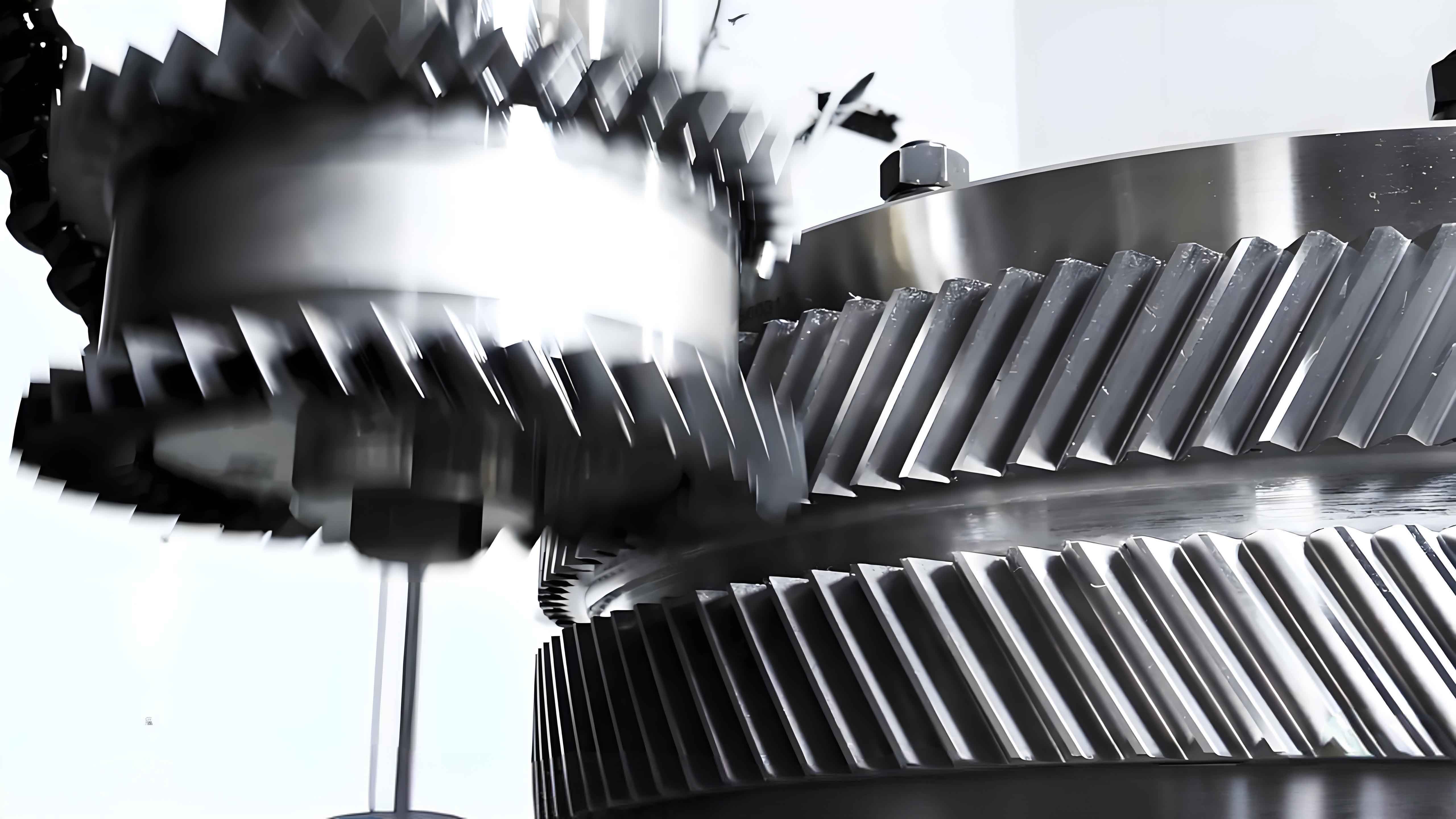
The successful machining of herringbone gears relies not only on practical steps but also on underlying theoretical principles. For instance, the tooth profile of herringbone gears follows an involute curve, which can be mathematically expressed. The equation of an involute curve in parametric form is given by:
$$ x = r_b (\cos(\theta) + \theta \sin(\theta)) $$
$$ y = r_b (\sin(\theta) – \theta \cos(\theta)) $$
where \( r_b \) is the base radius and \( \theta \) is the parameter. This geometry influences toolpath generation, as the cutter must follow this curve accurately. Additionally, cutting forces can be estimated using formulas such as:
$$ F_c = K_c \cdot a_p \cdot f_z \cdot z $$
where \( F_c \) is the cutting force, \( K_c \) is the specific cutting force, \( a_p \) is the depth of cut, \( f_z \) is the feed per tooth, and \( z \) is the number of teeth engaged. For herringbone gears, optimizing these parameters minimizes tool deflection and ensures dimensional accuracy. Another key aspect is the helical angle \( \beta \), which for herringbone gears is typically symmetric on both sides. The relationship between axial pitch \( p_a \) and normal pitch \( p_n \) is:
$$ p_a = \frac{p_n}{\cos(\beta)} $$
This affects the toolpath spacing and rotational synchronization during four-axis machining. To summarize critical parameters, Table 3 provides a comprehensive list of formulas and their applications in herringbone gear machining.
| Parameter | Formula | Description | Application in CNC |
|---|---|---|---|
| Involute Curve | \( x = r_b (\cos(\theta) + \theta \sin(\theta)) \), \( y = r_b (\sin(\theta) – \theta \cos(\theta)) \) | Defines tooth profile geometry | Toolpath generation for accurate tooth form |
| Cutting Force | \( F_c = K_c \cdot a_p \cdot f_z \cdot z \) | Estimates force during machining | Optimizing feeds and speeds to prevent tool breakage |
| Helical Angle Effect | \( p_a = p_n / \cos(\beta) \) | Relates axial and normal pitch | Synchronizing rotary axis motion with linear moves |
| Material Removal Rate (MRR) | \( \text{MRR} = a_p \cdot a_e \cdot v_f \) | Calculates volume removed per unit time | Assessing roughing efficiency for herringbone gears |
| Surface Roughness | \( R_a \approx \frac{f_z^2}{8 \cdot r_e} \) | Approximates average roughness | Selecting feed rates for finishing passes |
In terms of toolpath optimization, I leveraged NX’s advanced multi-axis strategies to address specific challenges of herringbone gears. For example, the “Rotary Part Roughing” strategy uses cylindrical layers that align with the gear’s axis, reducing tool engagement variations. The stepover distance \( s \) and cut depth \( d \) are calculated based on tool diameter \( D \) and allowable chip load \( c \):
$$ s = k \cdot D \quad \text{and} \quad d = \frac{F_c}{K_c \cdot f_z \cdot z} $$
where \( k \) is a factor typically between 0.5 and 0.8 for roughing. For finishing, the spiral toolpath ensures constant scallop height \( h \), given by:
$$ h = r – \sqrt{r^2 – \left(\frac{s}{2}\right)^2} $$
where \( r \) is the tool radius. By setting \( h \) to a minimal value (e.g., 0.01 mm), I achieved high surface quality on the herringbone gears. Additionally, the use of IPW in semi-finishing helps maintain uniform stock, but as noted, the morph raster pattern was preferred for smoother motion. The overall machining time \( T \) can be estimated by summing the times for each stage:
$$ T = \sum_{i=1}^{n} \frac{L_i}{v_{f,i}} $$
where \( L_i \) is the toolpath length for stage \( i \) and \( v_{f,i} \) is the feed rate. For our herringbone gear shaft, roughing accounted for approximately 60% of the total time, highlighting the importance of efficient toolpath generation.
The integration of four-axis machining with NX software has profound implications for herringbone gear production. It enables the加工 of complex geometries that are otherwise infeasible with dedicated gear cutters, especially for custom or low-volume applications. The advanced strategies reduce programming time by up to 40% compared to traditional methods, while improving accuracy through collision avoidance and optimized tool orientation. In practice, the machined herringbone gear shaft exhibited precise tooth profiles with surface roughness below 1.6 μm, meeting the stringent requirements of heavy machinery applications. This success underscores the versatility of multi-axis CNC systems for herringbone gears, which are critical in industries like mining, energy, and transportation.
Looking ahead, further advancements in CAM software and machine tools will continue to enhance the machining of herringbone gears. Potential areas include adaptive machining based on real-time sensor data, generative design for optimized tooth geometries, and the integration of artificial intelligence for automated parameter tuning. As an engineer, I believe that embracing these technologies will drive innovation in herringbone gear manufacturing, reducing costs and lead times while maintaining high quality. The experience detailed here serves as a foundation for future projects involving herringbone gears, demonstrating that with the right tools and strategies, even the most challenging components can be produced efficiently.
In conclusion, the machining of herringbone gears via four-axis CNC using NX software represents a significant leap in manufacturing capabilities. By leveraging advanced multi-axis strategies, meticulous process planning, and theoretical insights, I achieved high-precision results that validate this approach. Herringbone gears, with their unique double-helical design, demand such sophisticated methods to unlock their full potential in heavy-duty applications. As the industry evolves, continued focus on herringbone gears will undoubtedly yield further improvements, solidifying their role as indispensable components in modern machinery.