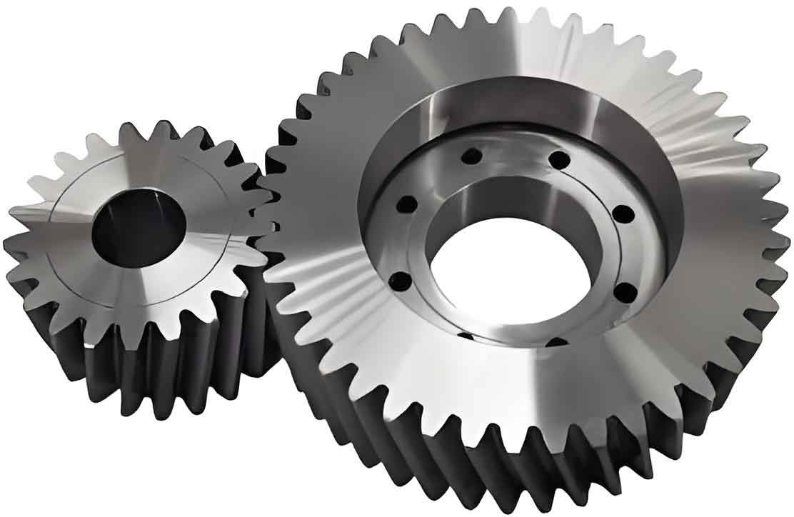
Spiral bevel gears are widely used in aerospace, automotive, and machinery due to their high load-bearing capacity, smooth transmission, and low noise. However, their complex tooth surface geometry and assembly requirements pose significant challenges in manufacturing and quality control. This paper explores innovative methods for meshing contact area detection and process optimization, with a focus on cylindrical gear applications.

1. Traditional Meshing Inspection Methods
The conventional coloring inspection process for spiral bevel gears involves applying marking compound and analyzing contact patterns. While effective for cylindrical gears, this method faces limitations when applied to complex geometries:
| Parameter | Cylindrical Gear | Spiral Bevel Gear |
|---|---|---|
| Contact Pattern Analysis | Linear contact | Elliptical contact |
| Measurement Error | ±0.05 mm | ±0.15 mm |
| Process Time | 15-20 min | 30-45 min |
The tooth contact pattern (TCP) for spiral bevel gears can be expressed as:
$$ TCP = \frac{1}{N} \sum_{i=1}^{N} (x_i – \bar{x})^2 $$
where \( x_i \) represents individual measurement points and \( \bar{x} \) is the mean contact pattern position.
2. Coordinate Measurement Technology
Modern CMM systems enable precise evaluation of gear tooth surfaces through grid-based measurement:
| Measurement Type | Resolution | Accuracy |
|---|---|---|
| Contact Probe | 5 μm | ±2 μm |
| Optical Scanning | 2 μm | ±1 μm |
The surface profile deviation (\( \Delta F_\alpha \)) for cylindrical gears is calculated as:
$$ \Delta F_\alpha = \max(z_i) – \min(z_i) $$
where \( z_i \) represents measured profile points along the tooth flank.
3. Process Control in Manufacturing
For cylindrical gear production, the following process parameters ensure quality consistency:
| Process Stage | Tolerance | Surface Finish (Ra) |
|---|---|---|
| Hobbing | IT7-IT8 | 3.2-6.3 μm |
| Grinding | IT4-IT5 | 0.4-0.8 μm |
The gear manufacturing process capability index (\( C_{pk} \)) is defined as:
$$ C_{pk} = \min\left(\frac{USL – \mu}{3\sigma}, \frac{\mu – LSL}{3\sigma}\right) $$
where \( USL \) and \( LSL \) are specification limits, \( \mu \) is process mean, and \( \sigma \) is standard deviation.
4. Fixed-Distance Assembly Methodology
The assembly dimension chain for cylindrical gears follows:
| Component | Tolerance | Contribution |
|---|---|---|
| Housing Bore | ±0.015 mm | 34% |
| Bearing Width | ±0.008 mm | 22% |
| Shim Thickness | ±0.005 mm | 18% |
The cumulative assembly error (\( \delta_{total} \)) is calculated as:
$$ \delta_{total} = \sqrt{\sum_{i=1}^{n} \delta_i^2} $$
where \( \delta_i \) represents individual component tolerances.
5. Intelligent Manufacturing Integration
For cylindrical gear production lines, real-time monitoring parameters include:
| Sensor Type | Measurement | Frequency |
|---|---|---|
| Vibration | 0-10 kHz | 1 ms |
| Thermal | 0-200°C | 100 ms |
| Acoustic | 20-20k Hz | 10 μs |
The system stability index (\( S \)) for cylindrical gear machining is expressed as:
$$ S = \frac{1}{T} \int_{0}^{T} |x(t) – \bar{x}| dt $$
where \( T \) is observation period and \( x(t) \) represents process variables.
6. Conclusion
The integration of coordinate measurement technology with traditional inspection methods significantly improves cylindrical gear quality control. Fixed-distance assembly methodology combined with intelligent monitoring systems ensures consistent meshing performance across aerospace and automotive applications. Future developments in cylindrical gear manufacturing will focus on adaptive machining algorithms and closed-loop quality assurance systems.
