
The pursuit of higher performance in precision power transmission, particularly for applications like industrial robotics and aerospace, has placed significant emphasis on the optimization of key transmission components. Among these, the rotary vector reducer stands out for its exceptional characteristics: high reduction ratio, compact structure, excellent torsional stiffness, and minimal backlash. At the heart of its second-stage transmission lies the cycloid-pin gear mechanism, where the profile of the cycloid gear directly governs critical performance metrics such as transmission accuracy, efficiency, load distribution, and operational lifespan. Consequently, researching optimal modification methods and their precise magnitudes for the cycloid gear tooth profile is of paramount practical importance for advancing the capabilities of the rotary vector reducer.
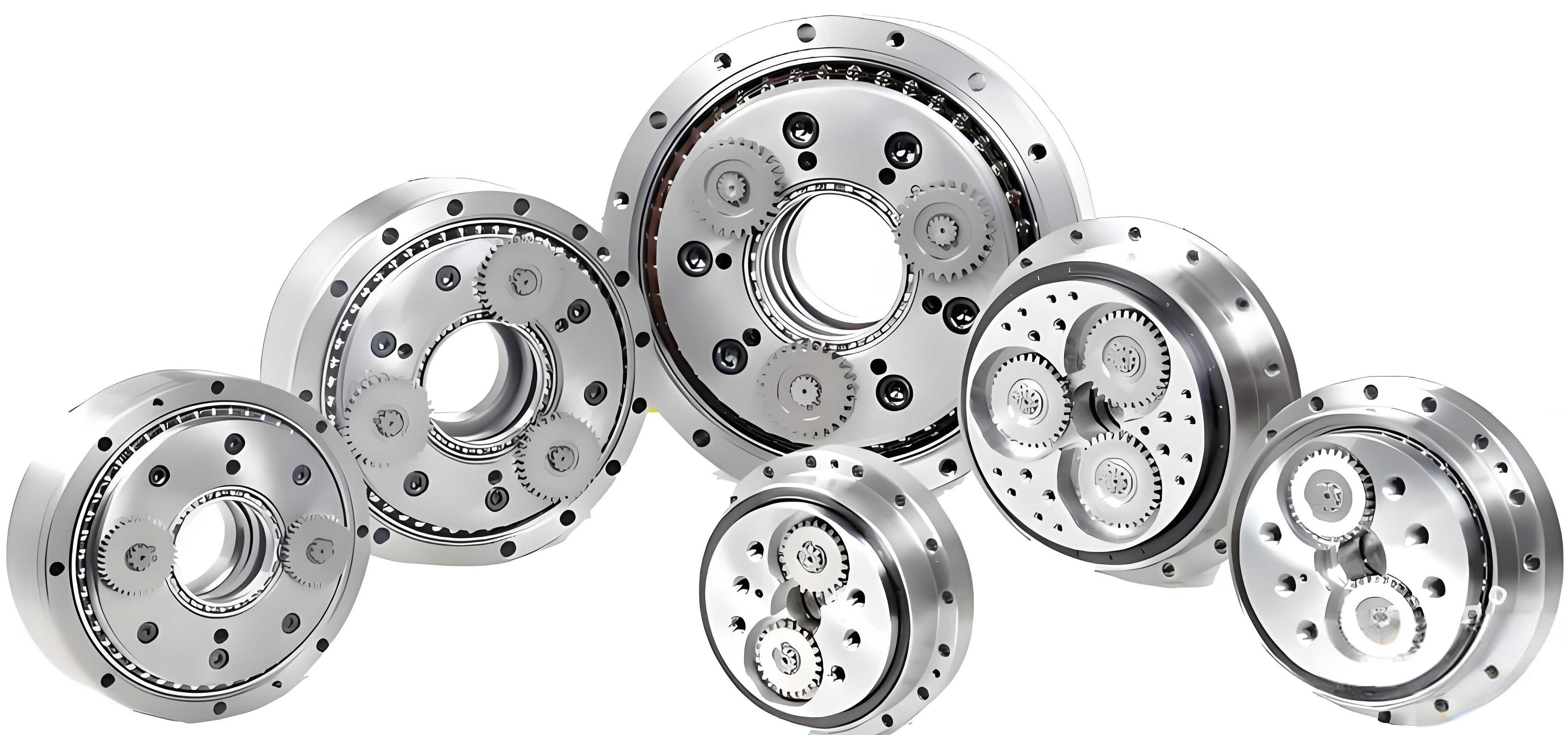
The fundamental mathematical model describing the cycloid gear profile is derived from its conjugate rolling motion with the pin teeth. In an ideal, zero-backlash scenario, the theoretical or standard tooth profile is generated. However, in practical manufacturing and assembly of a rotary vector reducer, modifications are essential to compensate for errors, ensure proper lubrication by creating oil pockets, and manage elastic deformations under load. The three primary basic modification methods are: equidistant modification, where the generating pin wheel radius is altered; profile shift modification, where the center distance of the generating process is modified; and rotation angle modification, where the theoretical rolling motion is offset by a small angle. Each method imparts distinct characteristics to the final tooth profile of the cycloid gear within the rotary vector reducer.
The standard profile and these modifications can be described by a unified set of parametric equations. Let us define the coordinate system with the center of the cycloid gear, $O_c$, as the origin, and the symmetry axis of a tooth trough as the $y$-axis. The coordinates $(x_c, y_c)$ of a point on the modified cycloid profile for a given rolling phase angle $\varphi$ are given by:
$$x_c = \left[ (r_p – \Delta r_p) – (r_{rp} + \Delta r_{rp}) \cdot S \right] \sin[(1-i_H)\varphi] – \frac{a i_H (r_p – \Delta r_p)}{(r_p – \Delta r_p) – (r_{rp} + \Delta r_{rp}) \cdot S} \sin(i_H \varphi + \delta)$$
$$y_c = \left[ (r_p – \Delta r_p) – (r_{rp} + \Delta r_{rp}) \cdot S \right] \cos[(1-i_H)\varphi] – \frac{a i_H (r_p – \Delta r_p)}{(r_p – \Delta r_p) – (r_{rp} + \Delta r_{rp}) \cdot S} \cos(i_H \varphi + \delta)$$
where the key parameters for the rotary vector reducer are defined in the following table:
| Symbol | Description | Unit |
|---|---|---|
| $r_p$ | Radius of the pin gear distribution circle | mm |
| $r_{rp}$ | Radius of the pin (before modification) | mm |
| $a$ | Eccentricity of the crankshaft | mm |
| $z_c$ | Number of teeth on the cycloid gear | – |
| $z_p$ | Number of pins ($z_p = z_c + 1$) | – |
| $i_H$ | Transmission ratio, $i_H = z_p / z_c$ | – |
| $\Delta r_{rp}$ | Equidistant modification amount | mm |
| $\Delta r_p$ | Profile shift modification amount | mm |
| $\delta$ | Rotation angle modification amount | rad |
| $K_1’$ | Modified shortcut coefficient, $K_1′ = a z_p / (r_p – \Delta r_p)$ | – |
| $S$ | Auxiliary variable, $S = (1 + K_1’^2 – 2K_1′ \cos \varphi)^{1/2}$ | – |
Among the basic methods, rotation angle modification produces a conjugate tooth profile, ensuring smooth meshing and theoretically constant transmission ratio. However, it fails to create essential radial clearance at the tip and root of the cycloid gear tooth, making it unsuitable for use alone in a practical rotary vector reducer. Conversely, equidistant and profile shift modifications are straightforward to implement in the grinding process and can be tailored to produce a controlled radial clearance. Therefore, combined modifications using these two methods are prevalent in industry. The choice of combination (positive/negative equidistant with positive/negative shift) significantly affects the initial meshing clearance between the cycloid gear and the pin, which in turn influences the number of simultaneously engaged tooth pairs and the overall torsional stiffness of the rotary vector reducer.
The initial clearance $\Delta_i$ along the common normal direction at the theoretical conjugate point for the $i$-th pin tooth, resulting from a combined equidistant and shift modification, is expressed as:
$$\Delta_i(\varphi_i) = \Delta r_{rp} \cdot \left( 1 – \frac{K_1 \sin \varphi_i}{\sqrt{1+K_1^2-2K_1 \cos \varphi_i}} \right) – \Delta r_p \cdot \left( \frac{1 – K_1′ \cos \varphi_i – \sqrt{1+K_1’^2-2K_1′ \cos \varphi_i} \cdot \sin \varphi_i}{\sqrt{1+K_1’^2-2K_1′ \cos \varphi_i}} \right)$$
where $K_1 = a z_p / r_p$ is the unmodified shortcut coefficient. Analyzing different sign combinations under a fixed total radial clearance $\Delta_r = \Delta r_{rp} + \Delta r_p$ reveals distinct clearance distribution patterns. For a typical rotary vector reducer configuration, the “positive equidistant + negative shift” combination yields the smallest initial clearance across a wide range of the meshing phase angle $\varphi_i$. This minimal initial gap brings the modified profile closer to the ideal conjugate one and promotes a higher number of tooth pairs in contact under light load, thereby maximizing the initial meshing stiffness—a critical property for the precision and rigidity of the rotary vector reducer.
Optimizing the modification solely based on initial clearance is insufficient. It is crucial to recognize that not the entire cycloid tooth profile is functionally engaged during operation. The actual working region is defined by the meshing entry and exit points with the pin teeth. Determining this region allows for targeted optimization where it matters most for the performance of the rotary vector reducer. The working region can be derived geometrically by analyzing the limit positions of contact. Considering the engagement with the $n_i$-th pin tooth, the corresponding meshing phase angle $\varphi(n_i)$ that defines the active portion of the cycloid tooth flank is given by:
$$\varphi(n_i) = \frac{2\pi n_i}{z_c} – \arccos\left( \frac{r_c’^2 + (M^2+N^2) – r_{rp}^2 \lambda^2}{2 r_c’ \sqrt{M^2+N^2}} \right)$$
for $n_i = 0, 1, …, z_p/2$, where:
- $r_c’ = a z_c$
- $\lambda = \frac{r_p S – r_{rp}}{r_{rp}}$
- $M = a – \frac{r_p’ + r_p \cos \alpha}{1+\lambda}$
- $N = \frac{r_p \lambda \sin \alpha}{1+\lambda}$
- $S = \sqrt{1+K_1^2-2K_1 \cos \alpha}$
- $\alpha = 2\pi n_i / z_p$
The angular span of the working region on the cycloid gear tooth, denoted $\gamma$, is related to the phase angle span by $\gamma = \varphi \cdot z_c / \pi$. For a standard rotary vector reducer design, calculations show that the working region typically covers a significant central portion of the tooth flank, excluding the very tip and root. Optimizing the profile specifically within this $\gamma$ range is the most efficient approach for enhancing the functional performance of the cycloid gear in the rotary vector reducer.
The proposed advanced strategy synthesizes the advantages of different modification methods. The goal is to employ a combined “positive equidistant + negative profile shift” modification (for high stiffness and manufacturable clearance) but to optimize its parameters such that, within the critical working region $\gamma$, the resulting tooth profile closely approximates the ideal conjugate profile generated by a small rotation angle modification $\delta$. This hybrid approach aims to deliver the smooth meshing characteristics of angle modification where the teeth are in contact, while retaining the practical benefits of radial clearance from the combined modification at the non-contact areas. This is formulated as a constrained optimization problem for the rotary vector reducer designer.
Let $L$ be the profile generated by a small, fixed rotation angle modification $\delta$. Let $L’$ be the profile generated by a combined modification with parameters $\Delta r_{rp} > 0$ and $\Delta r_p < 0$. For $m$ discrete sample points $x_i$ ($i=1,…,m$) spanning the working region $\gamma$, we obtain corresponding $y$-coordinates $y_i$ from $L$ and $y’_i$ from $L’$. The objective is to minimize the average absolute deviation between these profiles over the working region:
$$\min_{\Delta r_{rp}, \, \Delta r_p} F(\Delta r_{rp}, \Delta r_p) = \frac{1}{m} \sum_{i=1}^{m} |y_i – y’_i|$$
Subject to the following constraints essential for the rotary vector reducer:
- Radial Clearance Constraint: $\Delta r_{rp} + \Delta r_p = \Delta_r$, where $\Delta_r$ is the required total radial clearance (e.g., 0.005 mm for lubrication and error compensation).
- Modification Limit Constraint: $\Delta r_{rp} < \Delta_{max}$ (e.g., 0.02 mm) to prevent excessive backlash that would degrade the precision of the rotary vector reducer.
This non-linear optimization problem can be efficiently solved using metaheuristic algorithms such as the Genetic Algorithm (GA). The GA operates with a population of candidate solutions (pairs of $\Delta r_{rp}$ and $\Delta r_p$), iteratively applying selection, crossover, and mutation operations to evolve towards an optimal solution. The fitness of each candidate is evaluated by the objective function $F$. A typical convergence plot shows the minimum fitness value in the population decreasing over generations, indicating that the algorithm is successfully finding combined modification parameters that make $L’$ progressively closer to $L$ within the working region of the rotary vector reducer’s cycloid gear.
The optimal solution found by the GA for a sample rotary vector reducer configuration might yield values like $\Delta r_{rp}^* = 0.0170$ mm and $\Delta r_p^* = -0.0120$ mm for a target $\Delta_r = 0.005$ mm. The resulting profiles demonstrate the effectiveness of the strategy:
- Within the Working Region ($\gamma$): The optimized combined modification profile ($L’$) and the rotation angle modification profile ($L$) are virtually indistinguishable, ensuring near-conjugate, low-vibration meshing during the power transmission phase in the rotary vector reducer.
- At the Tooth Tip and Root: The optimized profile maintains the prescribed radial clearance $\Delta_r$ with respect to the standard conjugate profile, providing essential space for lubricant and compensating for manufacturing and alignment tolerances in the rotary vector reducer assembly.
The following table summarizes the comparative advantages of this optimized combined modification strategy over standard approaches for the rotary vector reducer:
| Aspect | Standard Combined Modification | Proposed Optimized Combination |
|---|---|---|
| Meshing Stiffness | Good (with “pos. equidistant + neg. shift”) | Excellent (maintained from base combination) |
| Meshing Smoothness in Working Zone | Moderate (deviation from conjugate profile) | High (approximates conjugate angle modification profile) |
| Radial Clearance Control | Good | Precisely controlled |
| Error Compensation | Yes | Yes, with optimized distribution |
| Design Focus | Often empirical or based on single-point contact | Systematic, targeting the entire functional engagement region |
In conclusion, the systematic approach to cycloid gear modification outlined here addresses multiple performance criteria for the rotary vector reducer. By first selecting the modification combination that maximizes initial meshing stiffness (“positive equidistant + negative profile shift”), then precisely defining the actual tooth working region through kinematic analysis, and finally employing numerical optimization to tailor this combination to approximate ideal conjugate action within that region, a superior tooth profile is achieved. This optimized profile for the rotary vector reducer ensures high stiffness, smooth and efficient power transmission where the teeth are in contact, and provides controlled clearance for lubrication and error accommodation elsewhere. This methodology provides a robust and effective framework for the design and manufacture of high-performance cycloid gears, directly contributing to the enhanced precision, reliability, and longevity of advanced rotary vector reducers used in demanding robotic and precision mechanical systems.
Future work could extend this model to explicitly include the effects of elastic deformation under load, aiming for a “loaded conjugate” profile that optimizes contact pressure distribution and further improves the load capacity and life of the rotary vector reducer. Multi-objective optimization considering trade-offs between stiffness, efficiency, and stress could also yield more comprehensive design guidelines for rotary vector reducer applications across different operational regimes.