
Gears are fundamental transmission components critical to industries like machinery, aerospace, and instrumentation. Compared to belt, chain, or hydraulic drives, gear transmissions offer superior precision, efficiency, load capacity, and durability. However, their complex geometry presents manufacturing challenges. Traditional dedicated gear hobbing machines face limitations due to aging equipment and declining precision, necessitating reduced cutting parameters that compromise productivity. This drives the adoption of CNC-based gear hobbing solutions.
Principles of Gear Hobbing
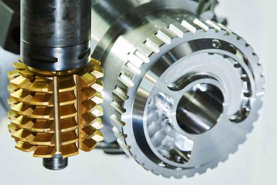
Gear hobbing operates on the generating motion principle, simulating meshing between two crossed helical gears. The hob—essentially a threaded worm with relieved flanks—rotates against the workpiece, progressively generating the tooth profile through synchronized motion. The kinematic relationship is defined by:
$$ \frac{N_{\text{hob}}}{N_{\text{gear}}} = \frac{\omega_{\text{gear}}}{\omega_{\text{hob}}} $$
where \(N_{\text{hob}}\) is the number of hob starts, \(N_{\text{gear}}\) is gear teeth count, and \(\omega\) represents angular velocities. For a single-start hob (\(\small{N_{\text{hob}} = 1\)), one hob revolution advances the workpiece by one tooth pitch. Key characteristics include:
- High material removal rates using multi-start hobs
- Fixed control parameters: center distance, axis coordinates, speeds, and feeds
- Complex cutting envelopes due to simultaneous multi-edge engagement
Process Parameters and Optimization
Successful gear hobbing requires precise hob setup and motion control. The hob installation angle \(\alpha\) ensures alignment between hob and workpiece helices. Its calculation depends on hob helix angle \(\lambda\) and gear helix angle \(\beta\):
$$ \alpha = \beta \pm \lambda $$
Direction signs (±) follow conventions in Table 1:
| Gear Type | Left-Hand Hob (\(\lambda\)) | Right-Hand Hob (\(\lambda\)) |
|---|---|---|
| Spur Gear | \(\alpha = \lambda\) (CCW) | \(\alpha = \lambda\) (CW) |
| Left-Hand Helical (\(\beta\)) | \(\alpha = \beta – \lambda\) (CW) | \(\alpha = \beta + \lambda\) (CW) |
| Right-Hand Helical (\(\beta\)) | \(\alpha = \beta + \lambda\) (CW) | \(\alpha = \beta – \lambda\) (CCW) |
Feed strategies significantly impact efficiency and tool life. Common methods include:
| Method | Characteristics |
|---|---|
| Axial | Stable cutting, low surface roughness, suitable for high feeds |
| Radial-Axial | Reduced cycle time, balanced tool life for moderate-width gears |
| Diagonal | Uniform tool wear, improved surface finish, requires specialized kinematics |
| Radial | Optimal for narrow gears with large-diameter hobs |
Cutting parameters follow empirical rules:
- Cutting passes: ≤3 (typically 1–2 roughing + finishing)
- Feed rate: Maximized within system rigidity limits; reduced for finishing
- Cutting velocity \(V_c\): Optimized for material and tool coating:
$$ V_c = \frac{\pi \cdot D_{\text{hob}} \cdot N_{\text{hob}}}{1000} \quad \text{(m/min)} $$
CNC Implementation with Electronic Gearbox
Modern CNC gear hobbing replaces mechanical gear trains with Electronic Gearbox (EGB) systems. EGB synchronizes axes via software-controlled coupling, enhancing precision and flexibility. For a turning-milling center, axis coupling is defined as:
EGDEF(C1, C13, 1, Z, 1)   // Couple C1 (workpiece) to C13 (hob)
EGON(C1, "NOC", C13, 1, -N_gear) // Ratio: Workpiece/Hob = -N_gear
where \(N_{\text{gear}}\) is tooth count. EGB advantages include:
- Eliminated mechanical transmission errors
- Adjustable transmission ratios without hardware changes
- Capability to produce non-standard gear profiles
Practical Application and Results
Implementing gear hobbing on a 5-axis turning-milling center involves:
- Mounting the hob (e.g., φ32mm M0.4) via dedicated toolholder (<0.01mm runout)
- Orienting milling spindle at calculated \(\alpha\)
- Programming radial-axial toolpath (Figure 7 schematic)
- Executing synchronized EGB motion
Testing demonstrated:
- Consistent dimensional accuracy for spur/helical gears
- 45%+ efficiency gain versus conventional methods
- Reduced programming effort via parametric routines
Conclusion
CNC-based gear hobbing with EGB overcomes limitations of dedicated machines, enabling high-precision gear production on multi-tasking platforms. Optimized kinematics, cutting strategies, and electronic synchronization ensure efficiency while maintaining quality. As CNC capabilities evolve, gear hobbing applications will expand further, underscoring its role in advanced manufacturing.