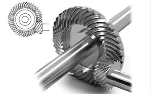
Spiral bevel gears are critical components for transmitting rotational motion between intersecting or staggered axes. With advantages such as high load capacity, smooth transmission, and efficiency, they are widely used in automotive, aerospace, and heavy machinery industries. This article explores key technologies and innovations in manufacturing large-scale spiral bevel gears (diameter ≥800 mm) with precision grades above 5.

1. Fundamental Concepts and Challenges
Large-scale high-precision spiral bevel gears require specialized manufacturing techniques due to their geometric complexity. The tooth profile follows a logarithmic spiral curve, described by:
$$ r(\theta) = r_0 e^{\theta \cot \beta} $$
where \( \beta \) is the spiral angle and \( r_0 \) is the initial radius. Key challenges include:
| Challenge | Impact |
|---|---|
| Tool-workpiece alignment | ±0.002 mm tolerance required |
| Heat treatment distortion | Surface hardness ≥58 HRC with <0.1% dimensional change |
| Surface finishing | Ra ≤0.4 μm for precision grades 3-5 |
2. Core Manufacturing Technologies
2.1 Traditional Face Milling
The cradle-type generation method remains prevalent for spiral bevel gear production. The process utilizes the following kinematic relationship:
$$ \frac{\omega_c}{\omega_w} = \frac{N_w}{N_c} $$
where \( \omega_c \) = cutter angular velocity, \( \omega_w \) = workpiece angular velocity, \( N_w \) = number of workpiece teeth, and \( N_c \) = number of cutter blades.
2.2 Cyclo-Palloid System
Modern Klingelnberg cyclo-palloid technology enables higher precision through constant tooth depth. Key parameters include:
$$ m_n = \frac{D_{pitch}}{N} \cos \beta $$
where \( m_n \) = normal module, \( D_{pitch} \) = pitch diameter, and \( N \) = number of teeth.
2.3 CNC Grinding Techniques
Post-heat treatment grinding achieves final precision using CBN wheels. The material removal rate (MRR) is calculated as:
$$ MRR = v_f \cdot a_e \cdot a_p $$
where \( v_f \) = feed speed (mm/min), \( a_e \) = radial engagement (mm), and \( a_p \) = axial engagement (mm).
3. Precision Enhancement Strategies
Advanced manufacturing approaches for spiral bevel gears include:
| Method | Accuracy Improvement | Efficiency Gain |
|---|---|---|
| Multi-axis CNC machining | ±15 arcsec → ±5 arcsec | Cycle time reduction 40% |
| Laser-assisted cutting | Surface roughness Ra 0.8→0.3 μm | Tool life 2× extension |
| Adaptive grinding | Tooth profile error <5 μm | Scrap rate reduction 70% |
4. Digital Manufacturing Integration
Modern spiral bevel gear production employs closed-loop digital systems:
$$ \text{Tolerance Stack} = \sqrt{\sum_{i=1}^{n} (k_i \cdot t_i)^2} $$
where \( k_i \) = sensitivity coefficient and \( t_i \) = individual tolerance component.
5. Future Development Trends
Emerging technologies for spiral bevel gear manufacturing include:
- Additive manufacturing for near-net-shape forging dies
- AI-based process parameter optimization
- In-process metrology integration
6. Conclusion
The advancement of large-scale high-precision spiral bevel gear manufacturing relies on synergistic development of:
$$ P = f(M,T,S) $$
where \( P \) = production capability, \( M \) = machine tools, \( T \) = cutting tools, and \( S \) = software systems. Continuous innovation in these domains will further enhance the performance and application scope of spiral bevel gears in modern industrial systems.
