Taking the working surface of a pair of spiral bevel gear pairs that can be paired (in which the large wheel is convex and the small wheel is concave) as an example to illustrate the two design methods of large coincidence proposed in this paper. The design parameters of the inner gear pair are shown in the design table of the diagonal gear pair and the inner gear pair. The preset parameters of meshing performance are the design coincidence degree ε R = 2.5. The transmission error amplitude of meshing conversion point of spiral bevel gear pair is δφ (TR) 2 = 20 ” and its symmetry is ς= 1. 0, and its type is required to be parabolic transmission error.
| Parameter | Large wheel convex surface | Small wheel concave (inner diagonal design) | Small wheel concave (along the tooth length) |
| Tip radius / mm | 94.235 0 | 93.442 4 | 92.028 6 |
| Tooth profile angle (/ °) | 22.5 | 22.5 | 22.5 |
| Radial tool position / mm | 114.785 3 | 105.747 6 | 87.872 6 |
| Angular tool position (/ °) | 48.769 4 | 47.429 1 | 49.998 1 |
| Roll ratio | 1.059 9 | 2.787 5 | 2.679 9 |
| Vertical wheel position / mm | 0.000 0 | 6.999 9 | 8.185 1 |
| Axial wheel position / mm | 0.000 0 | -3.485 3 | -4.049 5 |
| Bed / mm | 0.000 0 | 1.095 9 | 1.273 4 |
| Installation angle of wheel blank (/ °) | 68.222 9 | 18.328 1 | 18.328 1 |
| Second order variability coefficient | 0.000 0 | -0.085 0 | -0.123 6 |
| Third order variability coefficient | 0.000 0 | 0.196 8 | 0.283 5 |
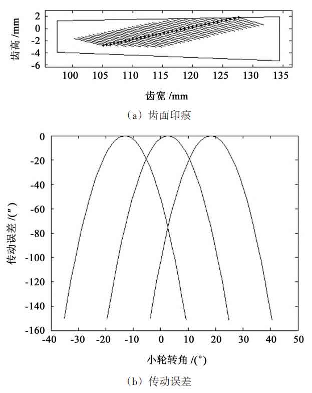
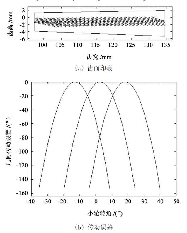
Figure 1 and Figure 2 show the tooth surface marks and transmission errors of the diagonal design in the contact path and the design along the tooth length, respectively. It can be seen from Figure 1 that when the inner diagonal design is adopted, the tooth surface impression gradually moves from the big end of the big wheel close to the tooth top to the small end close to the tooth root, showing an obvious inner diagonal shape; As can be seen from Fig. 2, when the design along the tooth length is adopted, the tooth surface impression spans the whole tooth surface from the big end of the big wheel to the small end of the big wheel. Comparing the transmission error curves in Figure 1 (b) and Figure 2 (b), it can be seen that the transmission error amplitude at the meshing conversion point is basically the same in the two designs. Similarly, in the degree of symmetry ς= In the parabola transmission error of 1.0, if the design coincidence degree ε R and its transmission error amplitude at the meshing conversion point δφ (TR) 2 is the same, then the transmission error amplitude at the meshing point and the meshing point is basically the same.