
Abstract
This paper focuses on the adjustment and correction of the contact area on the actual tooth surfaces of hypoid gears. Based on tooth surface measurements, a double cubic spline surface fitting method is employed for both pinion and gear tooth surfaces. A two-dimensional golden section method for refining tooth surface points is adopted, and a discrete tooth contact analysis algorithm is developed to obtain meshing information and contact pattern adjustment parameters of the actual tooth surfaces, providing a basis for the reversal adjustment of machine tool processing parameters. A rolling test on hypoid gear pair from an automotive axle is conducted, and the simulation analysis results are consistent with the actual rolling test, verifying the feasibility and correctness of the proposed algorithm.
1. Introduction
Hypoid gears are widely used in automotive axle transmissions due to their high contact ratio and smooth transmission. However, due to the complexity of their tooth surfaces and the cumbersome adjustment of machine tool processing parameters, controlling their meshing performance is challenging. The contact area on the tooth surface is related to vibration, noise, and operational smoothness of the gears. Deviations exist between the actual and theoretical tooth surfaces due to processing and installation errors. Adjusting the position of the contact area based on the rolling test results of the actual tooth surface contact pattern and subsequently revising the processing parameters are crucial steps in controlling the meshing performance of hypoid gears. Therefore, accurately fitting the actual tooth surface based on measurement results and conducting meshing performance analysis are prerequisites for adjusting and calculating the tooth surface processing parameters.
Table 1. Summary of Related Research
| Researcher | Focus | Method | Contribution |
|---|---|---|---|
| Chen et al. | Static unloaded transmission error | Experimental analysis | Investigated the impact on dynamic characteristics |
| Cao et al. | Decomposition algorithm for tooth contact analysis | Novel methodology | Improved computational efficiency |
| Su et al. | Optimization design of contact pattern stability | Experimental validation | Enhanced stability of contact patterns |
| Wang et al. | Sensitivity analysis and optimization | Numerical simulation | Provided insights into misalignment effects |
| Yang et al. | Lapping position control of real tooth surfaces | Experimental study | Improved lapping accuracy |
| Wu et al. | Tooth surface error correction | Numerical correction | Corrected errors in duplex helical method |
| Jiang et al. | Ease-off topological modification | CNC correction | Improved gear performance |
| Deng et al. | Accurate calculation of tooth surface deviation | Measurement technique | Enhanced measurement accuracy |
| Li et al. | Digital real tooth surface modeling | Non-geometric-feature segmentation | Improved modeling accuracy |
| Zhang et al. | Digital simulation of real tooth surfaces | NURBS-based simulation | Facilitated digital analysis |
| Du et al. | Contact analysis of real tooth surfaces | Experimental and numerical | Provided comprehensive contact information |
2. Fitting of Actual Tooth Surfaces
Based on the measurement results of the actual tooth surfaces of hypoid gears, the deviation values δij of the tooth surface measurement points are superimposed with the three-dimensional coordinates of the theoretical tooth surface points to obtain the coordinates of the real tooth surface points. The reconstruction of the actual tooth surfaces is performed using a double cubic NURBS surface fitting method.
Table 2. NURBS Surface Reconstruction Parameters
| Parameter | Description |
|---|---|
| S(u, v) | Reconstruction surface equation |
| Ki,j | Control points |
| wi,j | Weight factors |
| Ni,3, Nj,3 | B-spline basis functions |
| i, j | Control point indices |
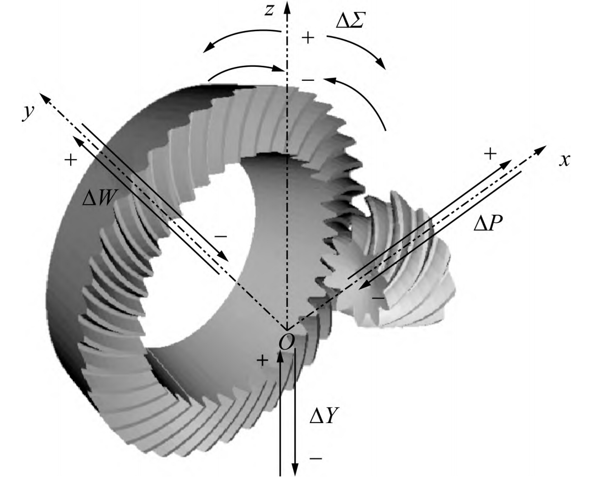
3. Adjustment Calculation Model for Installation Distance
The contact pattern on the actual tooth surface typically deviates from the preset position. To obtain the correction values for the processing parameters of the actual tooth surface, it is first necessary to adjust the position of the meshing points to obtain the adjustment amounts for the large wheel installation distance, small wheel installation distance, and offset distance when the contact point is at the desired position, and then convert them into actual machine tool processing correction values.
Table 3. Adjustment Parameters
| Parameter | Description |
|---|---|
| ΔV | Adjustment of large wheel installation distance |
| ΔH | Adjustment of small wheel installation distance |
| ΔJ | Adjustment of offset distance |
| γ1, γ2 | Pitch cone angles of small and large wheels |
| lMD | Midpoint cone distance of large wheel tooth surface |
4. Analysis of Actual Tooth Surface Contact Performance
For hypoid gear pairs, point contact meshing occurs at the meshing points. The distance between the tooth surfaces of the large and small wheels is zero at the meshing points and gradually increases along the tooth length and height directions. When the density of tooth surface grid points is sufficient, the minimum distance among all discrete points in the meshing area, when calculated, approximates the tooth surface distance.
4.1 Two-Dimensional Golden Section Refinement of Tooth Surface
The two-dimensional golden section method, based on the one-dimensional method, divides the feasible rectangular plane region in two dimensions by ratios of 0.618 and 0.382, compares the function values at the centers of the resulting small rectangles, and continues dividing the rectangle with the smallest function value until the size of the rectangle is less than the given accuracy.
4.2 Interference Judgment for Tooth Surface Meshing
The meshing state of tooth surface points is judged based on whether interference occurs between the two tooth surfaces, i.e., whether the dot product of the difference vector between a point on the large wheel tooth surface and the corresponding point on the small wheel tooth surface with the normal vector at the point on the small wheel tooth surface is less than 0.
5. Case Study Analysis
A hypoid gear pair from an automotive axle is used for calculation and solution according to the contact analysis algorithm shown in Figure 4. The basic parameters of the gear pair are listed in Table 4. The measurement results of the small and large wheel tooth surfaces are shown in Figure 5.
Table 4. Basic Parameters of Gear Pair
| Parameter | Small Wheel | Large Wheel |
|---|---|---|
| Number of teeth | 8 | 39 |
| Module / mm | 4.611 | 171.05 |
| Face width / mm | 25 | 30 |
| Offset distance / mm | 25 | – |
| Outer diameter / mm | 56.73 | – |
| Helix angle | Left-hand 50° | Right-hand 30°41′ |
| Pitch cone angle | 14°11′ | 76°49′ |
| Face cone angle | 18°10′ | 77°43′ |
| Root cone angle | 11°37′ | 70°48′ |
6. Conclusions
Based on the measurement results of the actual tooth surfaces of hypoid gears, the double cubic NURBS surface fitting method is used to reconstruct the tooth surfaces of both the pinion and gear. A contact performance analysis algorithm for actual tooth surfaces is developed based on the two-dimensional golden section method for refining tooth surfaces. This algorithm can quickly solve for tooth surface meshing trajectories, avoiding cumbersome solutions to nonlinear equations.