
Abstract This article focuses on the analysis and adjustment of the tooth contact of hypoid gears. It begins with an introduction to the importance and challenges of hypoid gear applications. The process of fitting the actual tooth surface using the double cubic NURBS surface method is described in detail, along with the installation distance adjustment calculation model. The contact performance analysis of the actual tooth surface, including methods such as two-dimensional golden section encryption and interference judgment, is presented. Through a case study, the effectiveness of the proposed methods is verified. The article concludes with a summary of the key findings and their implications for hypoid gear design and manufacturing.
1. Introduction
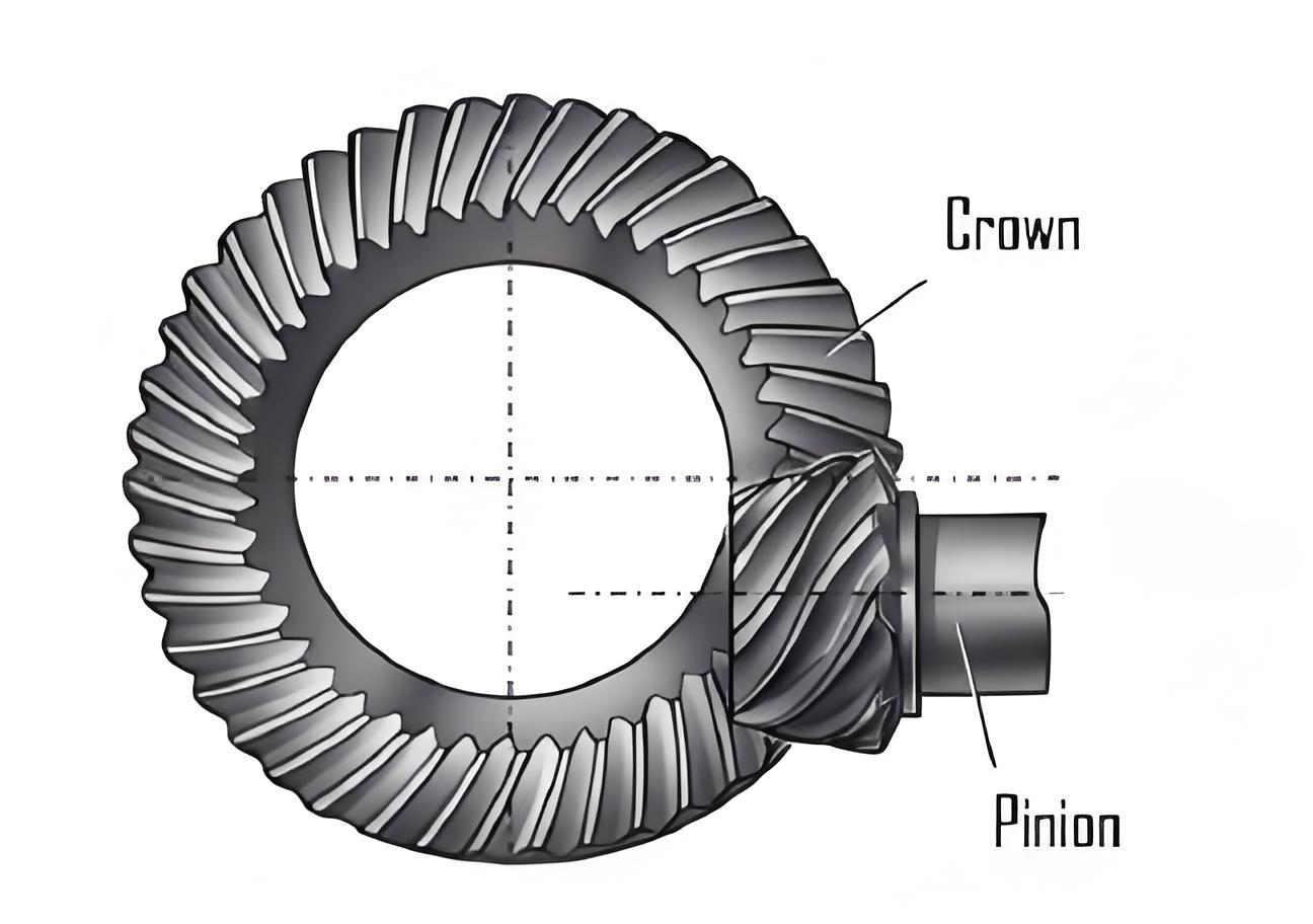
Hypoid gears are widely used in vehicle drive axle transmissions due to their large contact ratio and smooth transmission characteristics. However, the complex tooth surface and cumbersome adjustment of machine tool processing parameters make it difficult to control the meshing performance. The contact area of the tooth surface is related to the meshing performance such as vibration, noise, and running stability of the gear teeth. Due to the existence of processing and installation errors, there are deviations between the actual tooth surface and the theoretical tooth surface. Adjusting the position of the contact area based on the contact pattern rolling inspection results of the actually processed tooth surface and then correcting the processing parameters is a key step in controlling the meshing performance of hypoid gears. Therefore, accurate fitting of the tooth surface and analysis of the meshing performance based on the measurement results of the actual tooth surface are the prerequisites for adjusting the tooth surface processing parameters.
2. Actual Tooth Surface Fitting
2.1 Coordinate Calculation of Actual Tooth Points
According to the measurement results of the actual tooth surface of the hypoid gear, the deviation values δij of the tooth surface measurement points are superimposed on the three-dimensional coordinates of the theoretical tooth points to obtain the coordinates of the actual tooth points. The formula is
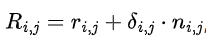
where i and j are the grid point numbers in the tooth height and tooth length directions respectively, Rij and rij are the position vectors of the grid points on the actual and theoretical tooth surfaces respectively, and nij is the unit normal vector of the grid points on the theoretical tooth surface.
2.2 Reconstruction of the Actual Tooth Surface using Double Cubic NURBS Surface
To conduct the actual tooth surface contact analysis, the double cubic NURBS surface construction method is adopted to reconstruct the actual tooth surface of the hypoid gear. The expression of the reconstructed tooth surface is .
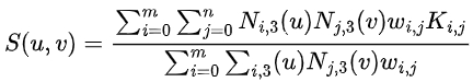
Here, Kij are the control points of the reconstructed tooth surface, i and j are the control point numbers with a total of (m+1)✖(n+1) points, wij are the corresponding weight factors, and Ni3 and Nj3 are the spline basis functions in the -direction (tooth length direction) and -direction (tooth height direction) respectively. Based on the measurement results of the tooth surface grid points, the control points of the NURBS curve are first calculated in the tooth height direction of the actual tooth surface, and then all the control points of the tooth surface are calculated in the tooth length direction to obtain the reconstructed actual tooth surface. According to the tooth surface measurement standard, the number of tooth surface grid points detected on the gear measurement center is (5 ✖ 9) points. When conducting the tooth surface contact analysis, interpolation and encryption processing of the control points are required according to the accuracy requirements to obtain accurate tooth surface meshing point positions.
3. Installation Distance Adjustment Calculation Model
3.1 Deviation of the Contact Pattern
The actual tooth surface contact pattern usually deviates from the preset position. Let M* and M0 be the actual and ideal contact positions respectively, and the distance coordinates of M* deviating from M0 are (s,t). In the coordinate system (O:X0;Y0), the coordinate of M* is (x2^*,y2^*), and there is a certain relationship between this point and the three-dimensional tooth surface coordinates (x2,y2,z2) of M0 in the coordinate system (O2: X2,Y2,Z2).
3.2 Establishment of the Meshing Relationship
Based on the rolling method of bevel gears, the meshing relationship between the large and small wheels is established. In the fixed coordinate system, the meshing of the large and small wheels on the tooth surface needs to satisfy certain relationships, including equations related to the position vectors of the meshing points, the unit normal vectors of the meshing points, and the relative motion speed at the meshing points. During the adjustment of the contact pattern position, the tooth side clearance needs to be kept constant, satisfying a specific equation.
3.3 Solution of the Adjustment Quantities
The equations involved contain multiple variables and are difficult to solve using conventional nonlinear solving methods. The Newton – Raphson iteration algorithm is adopted. By calculating the first-order partial derivatives of the 9 variables of the equation set, a matrix can be formed. Through iterative calculation, when the difference between two consecutive solutions is less than a certain precision, the solution of the equation set is obtained, which is the tooth surface coordinate of the meshing position. This position is used as the initial iteration point in the tooth surface contact analysis to find other meshing points by changing the rotation angles of the large and small wheels, thus forming the meshing trace of the tooth surface.
4. Actual Tooth Surface Contact Performance Analysis
4.1 Two-Dimensional Golden Section Encryption
In the optimization algorithm, the golden section algorithm has the advantages of simplicity, fast convergence speed, and significant effect. The two-dimensional golden section method is based on the one-dimensional algorithm. It divides the feasible plane rectangular area in two-dimensional directions with proportions of 0.618 and 0.382 respectively, and then compares the function values at the centers of each small rectangle after division. The rectangle area with the minimum function value is continuously divided until the size of the rectangle area is less than the given precision. The convergence of the two-dimensional golden section has been strictly proven mathematically. First, the initial meshing point positions of the large and small wheels are calculated, and then the area near the meshing points is encrypted using the two-dimensional golden section method according to the solution precision for different gear rotation angles to find the meshing points that meet the precision requirements.
4.2 Tooth Surface Meshing Interference Judgment
The meshing state of the tooth points is judged based on whether the two tooth surfaces interfere. That is, whether the inner product of the difference vector between the point on the large wheel tooth surface and the point on the small wheel tooth surface and the normal vector at the point is less than 0. If it is less than 0, the large and small wheel tooth surfaces interfere. The calculation process of the tooth surface meshing analysis includes steps such as calculating the initial meshing points, rotating the wheels, encrypting the control points in the meshing point area, judging the precision and interference, and ending when certain conditions are met.
5. Case Study
5.1 Gear Parameters and Measurement Results
The basic parameters of a hypoid gear pair of a vehicle axle are shown in Table 1. The measurement results of the tooth surfaces of the small and large wheels are presented.
| Parameter | Small Wheel | Large Wheel |
|---|---|---|
| Number of Teeth | 8 | 39 |
| Module (mm) | 4.611 | – |
| Tooth Face Width (mm) | 25 | – |
| Offset Distance (mm) | 25 | – |
| Outer Diameter (mm) | 56.73 | 171.05 |
| Helix Angle | 50° | 30’41’ |
| Pitch Cone Angle | 14’11’ | 76’49’ |
| Face Cone Angle | 18’10’ | 77’43’ |
| Root Cone Angle | 11’37’ | 70’48’ |
| Helix Direction | Left-handed | Right-handed |
5.2 Contact Analysis and Adjustment Results
According to the tooth surface meshing analysis and solution process, the transmission error curve and contact pattern of the actual tooth surface are obtained. The contact pattern of the convex surface of the large wheel is biased towards the large end. Based on the position of the contact pattern, the adjustment amounts of the indentation are determined approximately as a movement distance of 7 mm in the small end direction and a movement distance of 1 mm in the tooth top direction. Using a specific formula, the adjustment amounts of , , and are obtained as 0.312 mm, -0.433 mm, and 0.062 mm respectively. The contact analysis result after adjustment is presented. This adjustment amount can be converted into corresponding machine tool processing parameter correction amounts, such as tool position and wheel position corrections.
5.3 Verification of the Algorithm
The purpose of the tooth surface rolling inspection is to verify whether the position and shape of the actual tooth surface contact pattern meet the expected design requirements. To verify the correctness of the algorithm, the contact pattern rolling inspection results before and after the adjustment of the processing parameters are compared on a numerical control rolling inspection machine. The contact pattern of the actual convex surface of the large wheel is consistent with the simulation analysis result. The position of the contact area of the tooth surface after the correction of the processing parameters of the small wheel concave surface is also consistent with the theoretical analysis result, verifying the correctness of the model established in this article.
6. Conclusions
6.1 Summary of the Research
- Based on the measurement results of the actual tooth surface of the hypoid gear, the double cubic NURBS surface is used to reconstruct the tooth surfaces of the large and small wheels. Based on the two-dimensional tooth surface golden section encryption method, an algorithm for analyzing the contact performance of the actual tooth surface is developed. This algorithm can quickly solve the tooth surface meshing trajectory and avoid the cumbersome solution of nonlinear equation systems.
- The algorithm for analyzing the meshing performance of the actual tooth surface can replace the traditional rolling inspection test. Through the adjustment calculation results of the contact area, the corresponding tooth surface processing parameters can be adjusted in reverse.
6.2 Implications for Hypoid Gear Design and Manufacturing
The research results have important implications for the design and manufacturing of hypoid gears. The accurate fitting and analysis of the actual tooth surface can help improve the meshing performance of hypoid gears, reduce vibration and noise, and improve the reliability and service life of the gears. The adjustment method of the contact area can provide a basis for the correction of machine tool processing parameters, ensuring the quality of gear manufacturing. Future research can focus on further optimizing the algorithms and methods to adapt to more complex working conditions and higher precision requirements.