
Grinding cracks are a prevalent defect in gear manufacturing, particularly affecting carburized gears like those made from 20CrMnTi steel. These grinding cracks typically manifest as fine lines or networks perpendicular to the grinding direction, significantly compromising gear integrity and performance. In this analysis, I will explore the mechanisms, characteristics, experimental validation, and solutions for grinding cracks, drawing on metallurgical investigations and controlled trials to identify root causes and effective countermeasures.
The formation of grinding cracks stems from excessive thermal and mechanical stresses during grinding operations. When a grinding wheel interacts with the gear surface, frictional heat generates localized high temperatures, often exceeding critical thresholds. This heat causes rapid thermal expansion and contraction, inducing tensile stresses that exceed the material’s yield strength. The phenomenon can be modeled using the fundamental heat transfer equation: $$Q = k \cdot v \cdot f \cdot d$$ where \(Q\) is the heat input (in J/mm²), \(k\) is a material-specific constant, \(v\) is the grinding speed (m/s), \(f\) is the feed rate (mm/stroke), and \(d\) is the depth of cut (mm). Excessive \(Q\) leads to thermal gradients, producing stresses described by: $$\sigma = E \cdot \alpha \cdot \Delta T$$ Here, \(\sigma\) is the thermal stress (MPa), \(E\) is Young’s modulus (GPa), \(\alpha\) is the coefficient of thermal expansion (1/°C), and \(\Delta T\) is the temperature differential (°C). For 20CrMnTi steel, with typical values of \(E \approx 210\) GPa and \(\alpha \approx 12 \times 10^{-6}\) /°C, even moderate \(\Delta T\) of 200°C can induce stresses over 500 MPa, surpassing the material’s tensile strength and initiating grinding cracks.
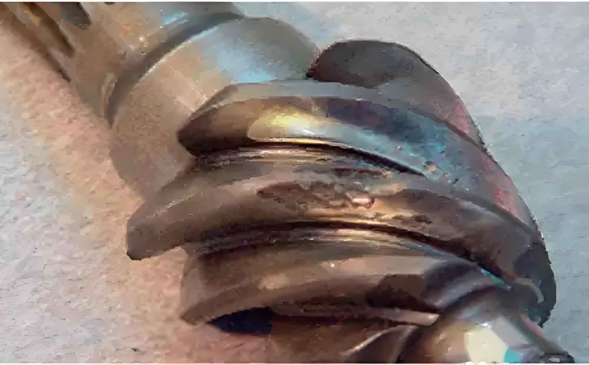
Grinding cracks exhibit distinct features: they are shallow (0.05–0.4 mm deep, occasionally reaching 0.8 mm), fine, and align orthogonally to the grinding path. Visual inspection often reveals accompanying temper colors or bluing due to oxidation. In gears, cracks appear as linear arrays or interconnected networks, as illustrated below. This visual evidence underscores the role of grinding heat in altering surface microstructure. For instance, the affected zones show untempered martensite and troostite instead of the desired tempered martensite, indicating thermal overloading. Such microstructural changes reduce hardness and promote crack propagation under operational loads.
Metallurgical standards for 20CrMnTi carburized gears specify surface hardness of 59–63 HRC, core hardness of 30–43 HRC, and a hardened case depth of 0.6–0.9 mm (550 HV3). Microstructure must adhere to QC/T262–1999, with carbides, retained austenite, and martensite graded per defined scales. Tables 1 and 2 summarize these grading systems, which are critical for assessing crack susceptibility. Abnormal microstructures, like untempered phases, directly correlate with grinding cracks due to inadequate heat dissipation during processing.
| Grade | Description |
|---|---|
| 1 | No or minimal carbides |
| 2 | Granular carbides, sparse distribution |
| 3 | Small blocky carbides, moderate quantity |
| 4 | Small blocky carbides with fine strings, abundant and deep |
| 5 | Blocky carbides, partially net-like |
| 6 | Large blocky carbides, discontinuous net |
| 7 | Large blocky carbides, continuous net |
| 8 | Coarse blocky carbides, dense continuous net |
| Grade | Retained Austenite (%) | Martensite Needle Size (mm) |
|---|---|---|
| 1 | <5 | <0.0030 |
| 2 | 10 | 0.0050 |
| 3 | 18 | 0.0080 |
| 4 | 23 | 0.0125 |
| 5 | 30 | 0.0200 |
| 6 | 37 | 0.0380 |
| 7 | 42 | 0.0600 |
| 8 | 50 | 0.0880 |
To pinpoint the causes of grinding cracks, I employed a fishbone diagram, categorizing factors into human, machine, material, method, environment, and measurement aspects. Primary contributors include insufficient cooling, deviations from grinding parameters, and thermal shocks from ambient conditions. Experimental trials were designed to validate these, with variables like cooling efficacy, double tempering, feed rate, and workpiece temperature. Tables 3, 4, and 5 detail the test setups and outcomes, demonstrating how cooling and tempering directly influence grinding crack incidence.
| Test ID | Cooling Status | Workpieces with Grinding Cracks | Crack Characteristics |
|---|---|---|---|
| 1 | Low flow, misaligned nozzle | 4 out of 8 | Deep (max 0.2 mm), multiple cracks |
| 2 | High flow, optimal positioning | 0 out of 4 | No cracks observed |
| Test ID | Tempering Process | Workpieces with Grinding Cracks | Crack Characteristics |
|---|---|---|---|
| 1 | Double tempering | 0 out of 10 | No cracks |
| 2 | Single tempering | 2 out of 10 | Fine, shallow (visually faint, ~1 mm long) |
| Test ID | Feed Rate (mm/stroke) | Ambient Adaptation | Workpieces with Grinding Cracks |
|---|---|---|---|
| 1 | 0.02 | 24-hour room temp stabilization | 0 out of 10 |
| 2 | 0.03 | 24-hour room temp stabilization | 0 out of 4 |
The trials confirm that grinding cracks are predominantly driven by thermal mismanagement. In Test 1 of Table 3, poor cooling resulted in a 50% crack rate, with depths up to 0.2 mm. This aligns with the heat equation, where low coolant flow elevates \(Q\), increasing \(\Delta T\) and \(\sigma\). Double tempering (Table 4) reduced grinding crack occurrence by stabilizing the microstructure through stress relief, as per the tempering kinetics: $$H = H_0 \cdot e^{-k t}$$ where \(H\) is hardness, \(H_0\) is initial hardness, \(k\) is a rate constant, and \(t\) is time. This process lowers residual stresses, diminishing crack initiation sites. Feed rate increases (Table 5) showed no cracks when combined with thermal equilibration, indicating that \(\Delta T\) control via ambient conditioning mitigates risks more than parameter adjustments alone.
Based on these findings, I recommend integrated solutions to suppress grinding cracks. First, optimize cooling systems to ensure high-volume, directed fluid flow at the grinding interface, reducing \(Q\) by at least 30%. Second, implement double tempering in the heat treatment cycle, which enhances stress uniformity and microstructural homogeneity. Third, enforce strict environmental controls: allow gears to acclimate to room temperature (e.g., >24 hours post-processing) before grinding to minimize thermal shocks. Additionally, maintain feed rates at ≤0.02 mm/stroke, as higher values could exacerbate heat buildup despite other mitigations. These measures collectively address the core issue of grinding heat, lowering \(\sigma\) to safe levels.
In conclusion, grinding cracks in 20CrMnTi carburized gears arise from uncontrolled grinding heat, leading to thermal stresses and microstructural degradation. Through systematic experimentation, I validated that cooling efficacy, double tempering, and thermal stabilization are critical for prevention. Adopting these strategies not only eliminates grinding cracks but also enhances gear durability and performance. Future work should explore real-time thermal monitoring and adaptive grinding controls to further refine crack mitigation in industrial settings.