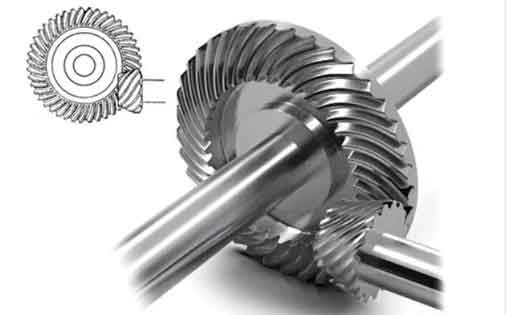
This paper presents a systematic approach for analyzing meshing misalignment in spiral bevel gear transmission systems under load conditions. The proposed methodology combines solid finite element analysis with multi-stage computational modeling to address the limitations of traditional beam element approaches.
1. Fundamental Definition of Meshing Misalignment
The relative displacement between spiral bevel gear pairs under load can be mathematically expressed as:
$$
\Delta P = (\mathbf{R}’ – \mathbf{R}_{OQ}) \cdot \mathbf{i} \\
\Delta W = (\mathbf{R}’ – \mathbf{R}_{OQ}) \cdot \mathbf{j} \\
\Delta E = (\mathbf{R}’ – \mathbf{R}_{OQ}) \cdot \mathbf{k} \\
\Delta \Sigma = \theta_2 – \theta_1
$$
Where ΔP represents axial displacement, ΔW denotes radial offset, ΔE indicates directional misalignment, and ΔΣ quantifies angular deviation from the ideal shaft crossing angle.

2. Comparative Analysis of Shaft Modeling Techniques
The accuracy of different shaft modeling approaches was evaluated through deformation analysis:
| Node | Model Type | X (μm) | Y (μm) | Z (μm) |
|---|---|---|---|---|
| 5 | Beam Element | 1.596 | 1.428 | 3.804 |
| Solid FEA | 1.765 | 1.543 | 4.983 | |
| 7 | Beam Element | 1.590 | 1.406 | 3.804 |
| Solid FEA | 1.785 | 1.540 | 4.983 |
The beam model showed average errors of 12.4% (input shaft) and 10.2% (output shaft) compared to solid FEA results, confirming the superiority of solid modeling for complex spiral bevel gear systems.
3. Stepwise Misalignment Analysis Methodology
The proposed three-stage analysis framework:
3.1 Shaft-Bearing Coupled Model
Bearing stiffness matrix implementation:
$$
\mathbf{K}_{bearing} = \begin{bmatrix}
k_x & 0 & 0 & 0 & 0 \\
0 & k_y & 0 & 0 & 0 \\
0 & 0 & k_z & 0 & 0 \\
0 & 0 & 0 & k_{\theta_y} & 0 \\
0 & 0 & 0 & 0 & k_{\theta_z}
\end{bmatrix}
$$
3.2 Equivalent Meshing Force Calculation
Force transformation for spiral bevel gears:
$$
F_{X’} = F_{mt}\sin\theta + F_{rd}\cos\theta \\
F_{Z’} = F_{mt}\cos\theta + F_{rd}\sin\theta \\
M_{Z’} = F_{ax}\sqrt{l^2 + l_{P1}^2}
$$
3.3 Loaded Tooth Contact Analysis
Transmission error calculation:
$$
TE = \frac{\theta_2 – (N_1/N_2)\theta_1}{2\pi} \times 60 \times 3600 \quad [\text{arcsec}]
$$
4. Case Study: Automotive Drive Axle Application
Key parameters for spiral bevel gear pair:
| Parameter | Pinion | Gear |
|---|---|---|
| Teeth | 7 | 43 |
| Module (mm) | 10.512 | |
| Pressure Angle | 22.5° | |
| Spiral Angle | 48.08° | 34.35° |
Misalignment results comparison:
| Parameter | Proposed Method | Full FEA | Error |
|---|---|---|---|
| ΔP (mm) | 0.0938 | 0.0952 | 1.47% |
| ΔE (mm) | -0.152 | -0.156 | 2.56% |
| ΔΣ (arcmin) | 1.986 | 2.022 | 1.78% |
5. Computational Efficiency Analysis
Performance comparison of different modeling approaches:
| Model Type | Elements | CPU Time (hr) |
|---|---|---|
| Proposed Method | 989,000 | 6.1 |
| Full FEA Model | 3,080,000 | 26.2 |
The stepwise approach achieved 76.7% reduction in computation time while maintaining 97.4% accuracy in spiral bevel gear misalignment prediction.
6. Conclusion
The developed methodology provides an effective solution for analyzing spiral bevel gear transmission systems, combining computational accuracy with practical efficiency. Key advantages include:
- Superior deformation modeling through solid FEA
- Accurate bearing stiffness coupling implementation
- Efficient multi-stage analysis framework
This approach enables precise tooth contact optimization and transmission error correction in spiral bevel gear design, particularly beneficial for automotive and aerospace applications requiring high-power density gearing solutions.
