
In my extensive experience with textile machinery maintenance, I have repeatedly encountered a specific and persistent failure point in certain models of lap-forming machines. The issue centers on the spiral gear shaft responsible for transmitting motion from the upper to the lower cone drum. The original design, as I observed it, featured a monolithic cast component integrating the shaft, its supporting bracket (or foot), and an adjustment nut. This shaft, acting as a cantilever to support the spiral gears, consistently failed at the fillet or shoulder region where it met the larger body of the bracket. This failure mode, characterized by brittle fracture, rendered the entire complex casting unusable and presented significant repair challenges, often leading to prolonged machine downtime. This analysis details my systematic investigation into the root cause and the subsequent development of a robust, modular solution.
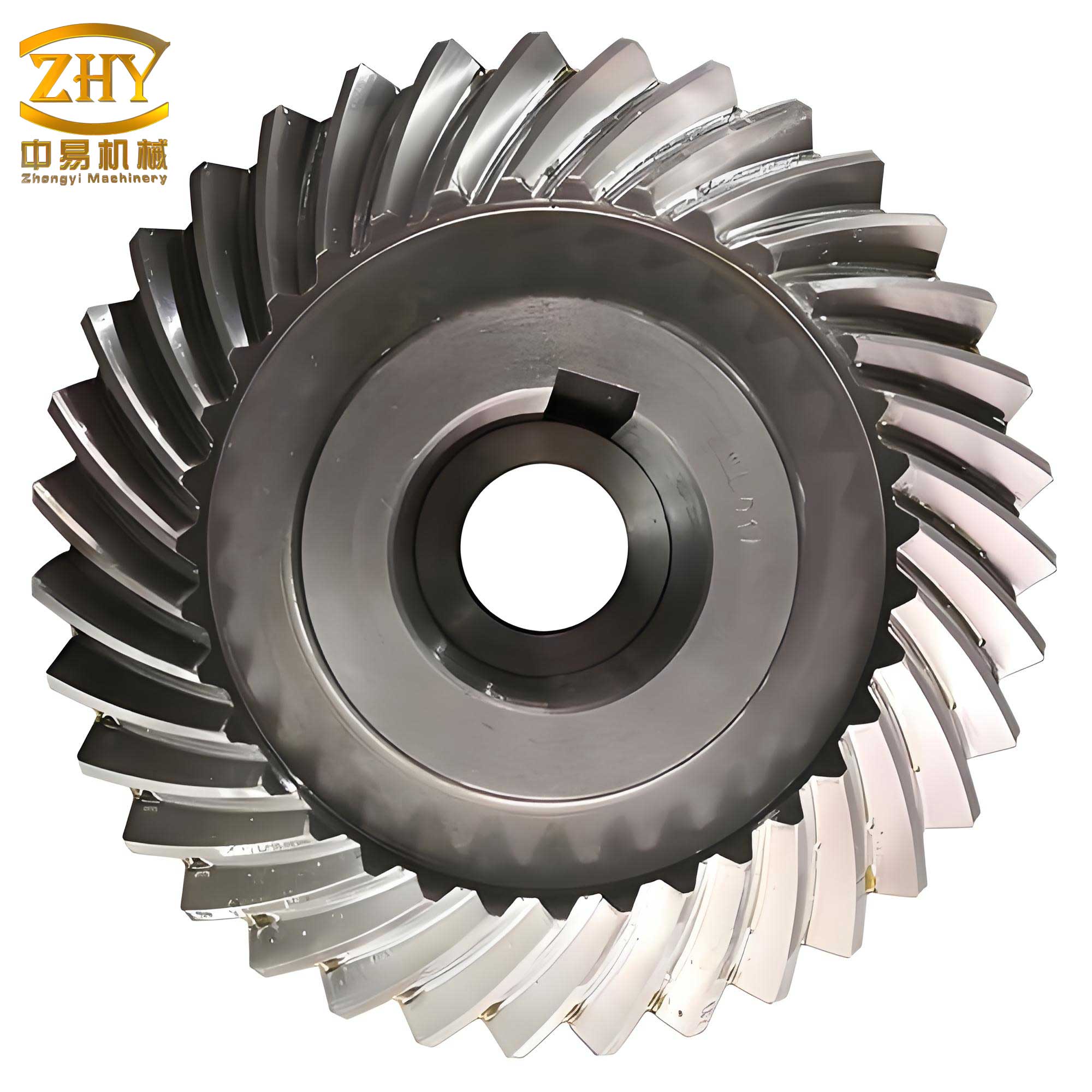
The primary function of this assembly is to reliably transmit rotational force and motion. The spiral gears are crucial here, as their angled teeth provide smoother and quieter engagement compared to straight-cut gears, which is vital for the precise control required in regulating lap weight and uniformity. However, this advantage is nullified if the supporting structure is weak. The original cast iron shaft, while sufficient for compressive loads, performs poorly under cyclic bending stresses. The geometry creates a classic stress concentration scenario at the shoulder. The bending moment (M) at the failure point can be expressed as:
$$ M = F \times L $$
where F is the resultant force from the gear mesh (a combination of tangential and radial components from the spiral gears) and L is the overhang length of the shaft. The bending stress (σ_b) is then:
$$ \sigma_b = \frac{M \cdot c}{I} $$
where c is the distance from the neutral axis to the outer fiber (equal to the radius d/2) and I is the area moment of inertia. For a solid circular shaft, I is given by:
$$ I = \frac{\pi d^4}{64} $$
Therefore, the maximum bending stress becomes:
$$ \sigma_{b,max} = \frac{32 M}{\pi d^3} $$
This equation clearly shows that stress is inversely proportional to the cube of the shaft diameter at the critical section. The original cast shaft’s diameter at the shoulder was constrained by the surrounding assembly, limiting its ability to withstand the calculated cyclic loads. Furthermore, the fatigue strength of the cast material is significantly lower than that of forged or rolled steel. The combination of high stress concentration, inadequate diameter, and suboptimal material choice was the fundamental cause of failure.
| Parameter | Symbol | Value (Original) | Unit | Notes |
|---|---|---|---|---|
| Overhang Length | L | ~65 | mm | Estimated from assembly |
| Shaft Diameter at Shoulder | d | ~20 | mm | Critical failure point |
| Estimated Gear Force | F | 800 – 1200 | N | Varies with load |
| Calculated Bending Moment | M | 52 – 78 | N·m | M = F * L |
| Calculated Max Bending Stress | σ_b,max | 33.1 – 49.7 | MPa | Using formula above |
| Fatigue Limit (Cast Iron) | σ_e | ~40 – 60 | MPa | Highly variable, includes stress concentration factor (Kt >> 1) |
My first redesign attempt aimed for a simple repair. I manufactured a new short shaft from high-strength 45-grade steel and attempted to join it to the remaining original bracket using an interference fit supplemented with industrial adhesive. The calculation for the required interference fit pressure (p) was based on the torque transmission requirement:
$$ p = \frac{2T}{\mu \pi d^2 l} $$
where T is the torque from the spiral gears, μ is the coefficient of friction, d is the shaft diameter, and l is the engagement length. While theoretically sound, this approach overlooked a practical weakness: the thin-walled nature of the cast bracket’s hub in the shoulder region. Although the new steel shaft was strong, the surrounding cast iron could not withstand the resulting hoop stresses and localized pressure, leading to crack initiation and propagation. The assembly failed catastrophically after a few months of operation, with the short shaft detaching completely. This failure underscored that the strength of the entire system is limited by its weakest link—in this case, the cast bracket’s hub.
The lesson learned led to the conception of a three-component modular assembly. This redesign completely abandons the monolithic casting philosophy. The system is now decomposed into three distinct, purpose-made parts: a modified bracket, a dedicated short shaft, and a separate locking nut. This modularity is the key to reliability and serviceability. The modified bracket is salvaged from the original part by machining out the failed shaft portion, leaving a clean, through-hole. This eliminates the stress-concentrating shoulder entirely. The new short shaft is turned from 40Cr alloy steel, a material with excellent tensile strength and fatigue resistance, far superior to cast iron for this application. Its diameter can be optimized based on the bending stress formula, and it features a threaded section at one end. The new locking nut, machined from standard #45 steel, secures the entire assembly axially.
The engineering specifications for the successful three-piece assembly are detailed below. The shaft-to-bracket connection now uses a light interference fit (e.g., H7/p6) over a precisely controlled engagement length. Crucially, this engagement length (l_engage) is designed to be slightly less than the total thickness of the bracket (t_bracket). This ensures the fit is contained within the strongest section of the bracket and avoids creating a new stress point at the exit. The assembly procedure is straightforward: press the steel shaft into the bracket’s hub, mount the spiral gears, and secure everything with the locking nut. The torque required to tighten the nut generates a clamping force that further stabilizes the assembly without relying on the brittle strength of cast iron.
| Component | Material | Key Dimensions / Spec | Critical Function |
|---|---|---|---|
| Modified Bracket | Original Cast Iron (reused) | Through-hole diameter: d_hole (H7). Bracket thickness: t_bracket. | Provides structural support and alignment. No longer a cantilever root. |
| Short Shaft | 40Cr Alloy Steel | Fit diameter: d_shaft (p6). Length l_engage < t_bracket. Thread: Mxx. | Core load-bearing member. Transmits all torsional and bending loads from spiral gears. |
| Locking Nut | #45 Carbon Steel | Thread: Mxx. Wrench flats for tightening. | Provides axial preload and security, prevents shaft walkout. |
The performance improvement can be quantified by comparing the stress states. In the new design, the dangerous bending stress is calculated for the uniform-diameter steel shaft at the point where it exits the bracket support. Using a slightly larger diameter (d_new) and a superior material yield strength (S_y,steel), the safety factor (N) increases dramatically:
$$ \sigma_{b,new} = \frac{32 M}{\pi d_{new}^3} $$
$$ N_{new} = \frac{S_{y,steel}}{\sigma_{b,new}} \quad \text{vs.} \quad N_{old} = \frac{S_{u,cast} / k}{\sigma_{b,old} \cdot K_t} $$
where k is a factor for cast iron’s lower ratio of fatigue to tensile strength, and K_t is the stress concentration factor (significantly greater than 1 for the old shoulder). The new design eliminates K_t and utilizes a material with a more favorable S_y. Furthermore, the modular design introduces unparalleled maintainability. Should the shaft wear or the threads damage—common issues in high-use environments—only the simple, low-cost short shaft needs replacement. The more complex bracket remains intact. This drastically reduces spare parts inventory cost and machine downtime. The reliability of this solution has been confirmed over extended operational periods, with no recurrence of the fracture failure previously endemic to these spiral gear drives.
The principles of this redesign—replacing monolithic, stress-concentrating cast assemblies with modular, steel-based components—have broad applicability. Similar spiral gear shaft arrangements on other series of lap-forming machines and related textile machinery suffer from identical design flaws. The three-piece solution is universally adaptable because it addresses the fundamental mechanical shortcomings rather than the specifics of a single model. By applying the same analytical process—identifying the load case (bending from spiral gear forces), calculating stresses, selecting appropriate materials (high-strength steel vs. cast iron), and designing for maintenance—this approach can prevent recurrent failures across many machine types. It stands as a testament to the power of first-principles engineering analysis over simple part-for-part replacement, ensuring that the critical motion from the spiral gears is transmitted smoothly and reliably for the long term.