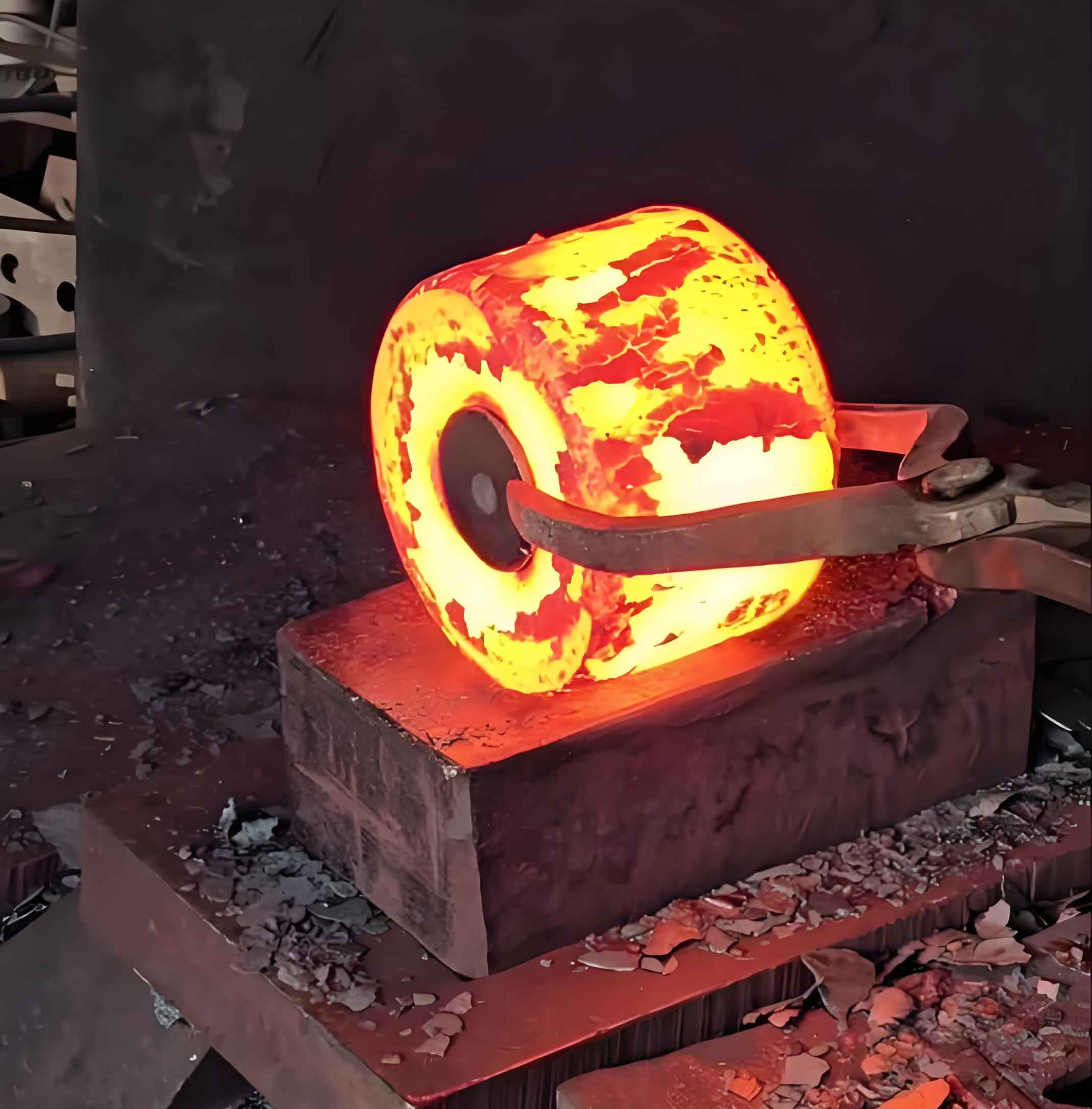
Folding represents a critical defect in gear forging manufacturing, occurring when oxidized metal surfaces converge and embed internally during deformation. This defect compromises structural integrity by creating stress concentration points that often lead to catastrophic failures. The following analysis details the root causes and resolution of folding defects encountered during production of 20CrMnTi transmission second shaft gears.

Defect Manifestation and Metallurgical Analysis
Post-carburization machining revealed circumferential defects near bore regions in 6% of production units. Metallographic examination showed:
- Blunt termination morphology (vs. sharp crack propagation)
- Inclusion bands within defect zones
- Decarburization evidence in adjacent material
The defect formation energy follows the strain energy relationship:
$$ E_f = \int_0^{\varepsilon} \sigma_f d\varepsilon $$
where $\sigma_f$ represents flow stress and $\varepsilon$ effective strain.
Systematic Root Cause Analysis
| Potential Cause | Investigation Method | Conclusion |
|---|---|---|
| Raw material defects | Surface topology scanning | Random distribution ≠ localized defect |
| Cutting-induced imperfections | End-face metrology | Shear-free sawing eliminated burrs/concavity |
| Metal flow abnormalities | DEFORM 2D simulation | Primary folding mechanism confirmed |
Metal Flow Dynamics in Gear Forging
Finite element analysis revealed critical flow imbalances during final forging:
- Velocity differential between web ($v_w$) and flash zone ($v_f$):
$$ \Delta v = v_f – v_w \geq 8.2 \text{ mm/s} $$ - Strain rate divergence at transition radius:
$$ \dot{\varepsilon}_r = \frac{\partial v_r}{\partial r} $$
Simulation results demonstrated metal reflux patterns causing surface entrapment at the web-flash junction. This folding initiation occurs when:
$$ \frac{v_f}{v_w} > 1.6 $$
Die Modification Strategy
Geometric redesign addressed flow imbalances through:
| Parameter | Original (mm) | Optimized (mm) | Improvement |
|---|---|---|---|
| Transition radius | R5 | R8 | 60% increase |
| Flash land depth | 3.0 | 6.2 | 107% increase |
| Web thickness | 4.8 | 5.2 | 8.3% increase |
The velocity gradient reduction achieved through radius modification follows:
$$ \nabla v_{new} = \nabla v_{old} \times \left( \frac{r_{old}}{r_{new}} \right)^{1.2} $$
Validation and Implementation
Post-modification simulation showed:
- Velocity differential reduction: $\Delta v \leq 2.4 \text{ mm/s}$
- Flow angle optimization: $\theta < 35^\circ$ (vs. original $52^\circ$)
- Strain homogenity increase:
$$ H_{\varepsilon} = 1 – \sqrt{\frac{\sum(\varepsilon_i – \bar{\varepsilon})^2}{n}} \geq 0.87 $$
Production verification demonstrated 100% elimination of folding defects, validating the gear forging process optimization. The solution reduced scrap rate from 6% to near-zero while maintaining dimensional specifications.
Technical Recommendations for Gear Forging
Preventative measures for similar components:
- Maintain radius-to-thickness ratio: $ R/t \geq 0.16 $
- Control metal velocity ratio: $ 0.8 \leq v_f/v_w \leq 1.3 $
- Implement pre-forging when volume distribution $ V_{web}/V_{flange} < 0.4 $
The folding prevention criterion can be generalized as:
$$ \Psi = \frac{R \cdot v_w}{t \cdot v_f} \geq 0.45 $$
where $\Psi$ represents the forging stability index.
This systematic approach to gear forging defect resolution demonstrates how targeted die modifications, guided by computational modeling, effectively eliminate folding while enhancing process robustness. The methodology provides a transferable framework for complex forging production optimization.
