The whole meshing process of a single pair of teeth is divided into 30 positions to complete the calculation, and the big wheel rotates 1 ° at each position. The mechanical results required for analysis can be obtained through finite element post-processing.
1. Contact force and comprehensive elastic deformation of gear teeth
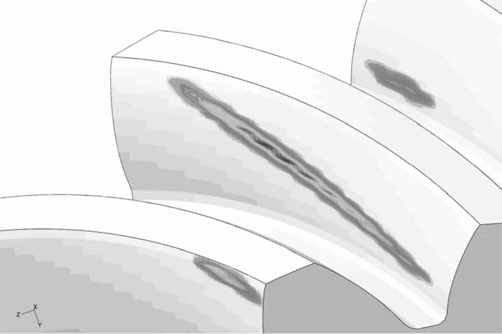
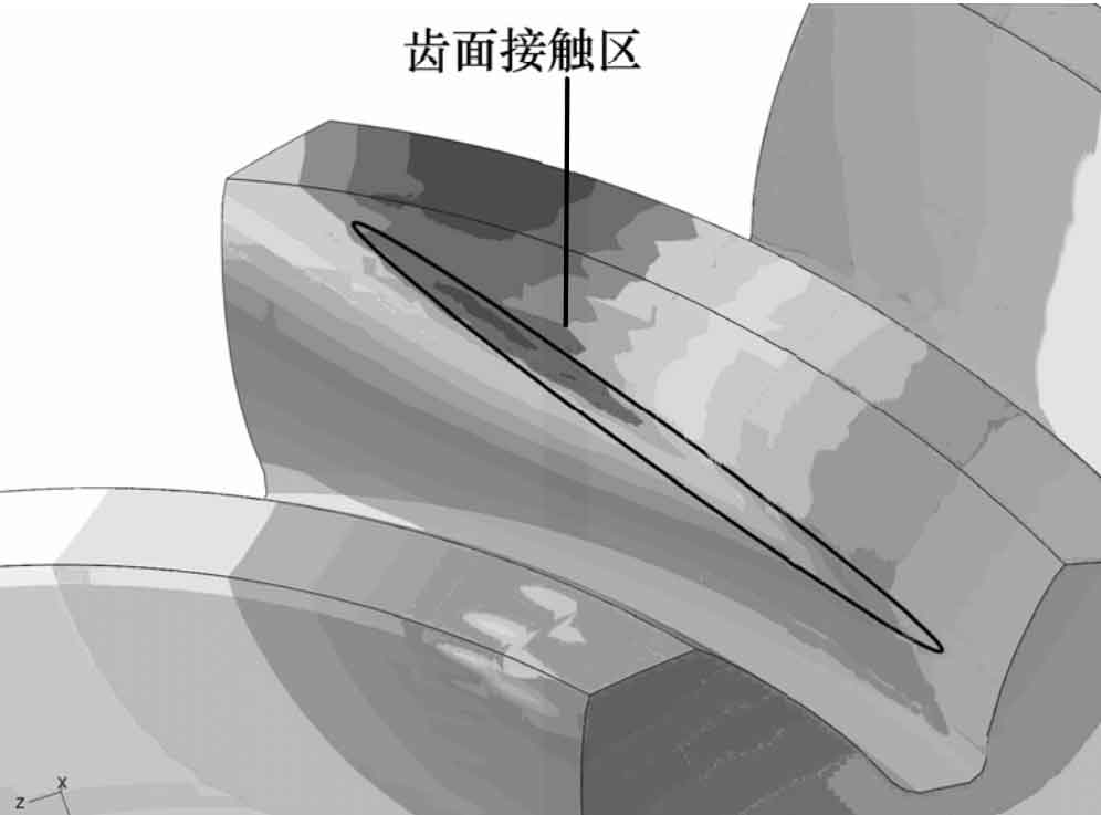
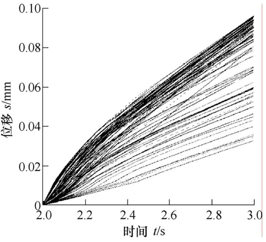
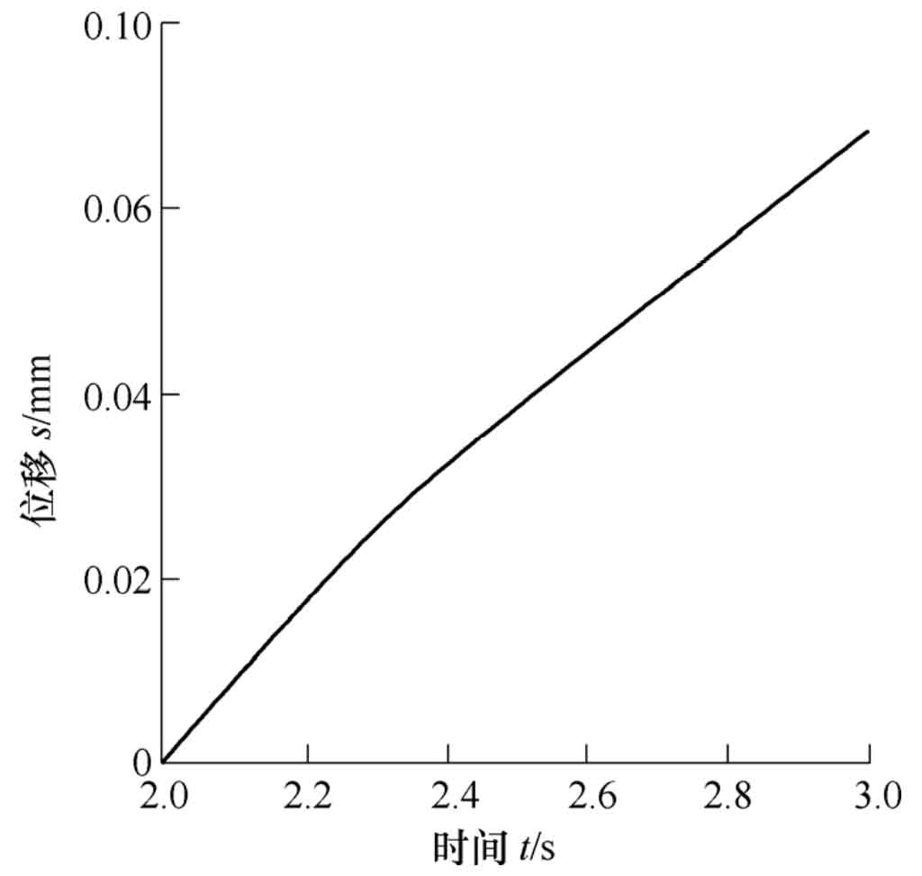
Taking the intermediate teeth of five teeth as the analysis object, figure 1 is the cloud diagram of tooth surface contact force. It can be seen from Figure 1 that the tooth surface contact area is a long ellipse and inclined to the tooth surface when the spiral bevel gear is loaded and contacted. Through the post-processing function of ABAQUS software, the contact force resultant force of the intermediate teeth is output as the historical variable, and the change of the contact force with time can be obtained, as shown in Figure 2. Fig. 3 is the comprehensive elastic deformation cloud diagram of gear teeth. It can be seen from Fig. 3 that the comprehensive elastic deformation of each point in the contact area of gear surface is different. It is necessary to take the average value of each displacement value, extract the node with contact force greater than 0, draw its deformation displacement curve, as shown in Fig. 4, and then use the average value processing function of the software to obtain the average displacement curve, as shown in Fig. 5. The maximum values in figures 2 and 5 are the final results of finite element iterative calculation, that is, FN and UN in the formula.

2. Single tooth meshing stiffness calculation
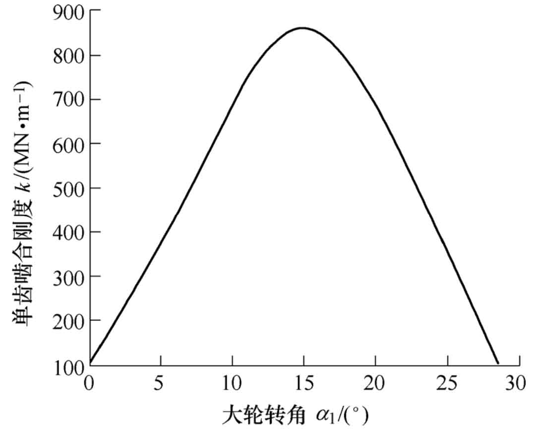
After the normal contact force FN and the comprehensive elastic deformation UN of the gear teeth are obtained through the finite element calculation, the single tooth meshing stiffness at each contact position is calculated by the formula, and the single tooth stiffness curve is interpolated by the 30th degree polynomial, as shown in Fig. 6.
3. Calculation of coincidence degree of spiral bevel gear
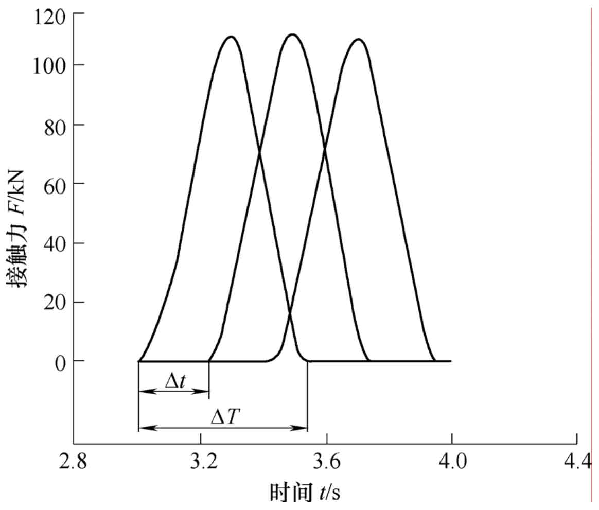
After obtaining the single tooth meshing stiffness, it is necessary to calculate the multi tooth comprehensive meshing stiffness by stacking the single tooth stiffness after translation according to the coincidence degree. During the loading and rotation of the gear, when the tooth pair enters the meshing, the normal contact force will inevitably be generated on the tooth surface. Within the elastic range, the normal contact force will disappear immediately once the gear teeth exit the mesh. The time of contact force from generation to disappearance is the time when the gear teeth actually participate in meshing. By measuring the time difference ∆ t between a single tooth participating in meshing and the time difference ∆ t between the two adjacent teeth starting meshing (or exiting meshing), the coincidence degree is:
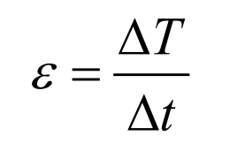
The variation curve of the contact force of the middle three pairs of teeth with time is obtained through finite element post-processing, as shown in Fig. 7. It can be obtained that ∆ = t 0.53 s, 0.21 s ∆ = t, which can be obtained from the formula ε = 2.524 。
4. Calculation of multi tooth comprehensive stiffness of spiral bevel gear
Move the single tooth meshing stiffness analysis to the left and right angle n ∆ α The meshing stiffness of each tooth pair can be obtained, as shown in Figure 8, ∆ α The calculation formula is:
Where, φ In order to complete the whole meshing process, the rotation angle of the big wheel.
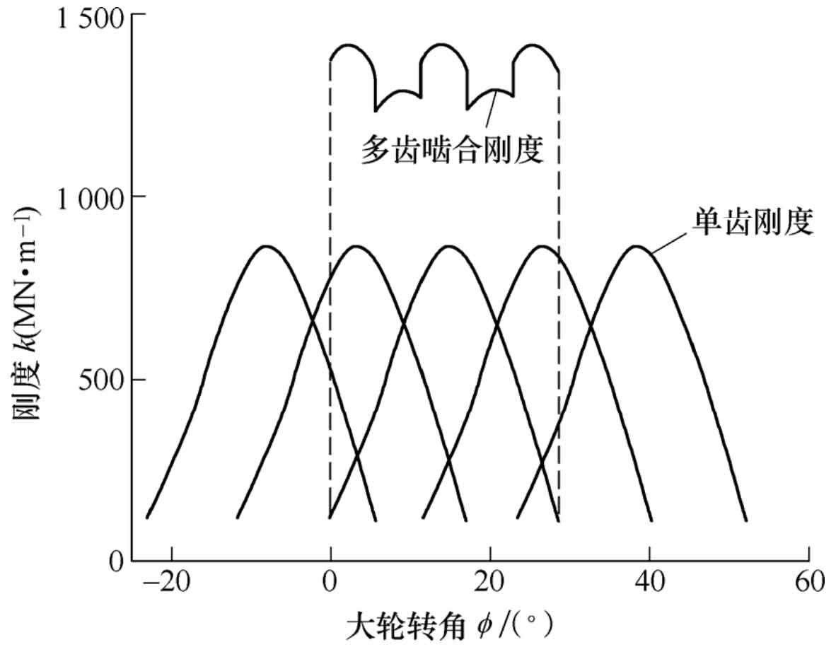
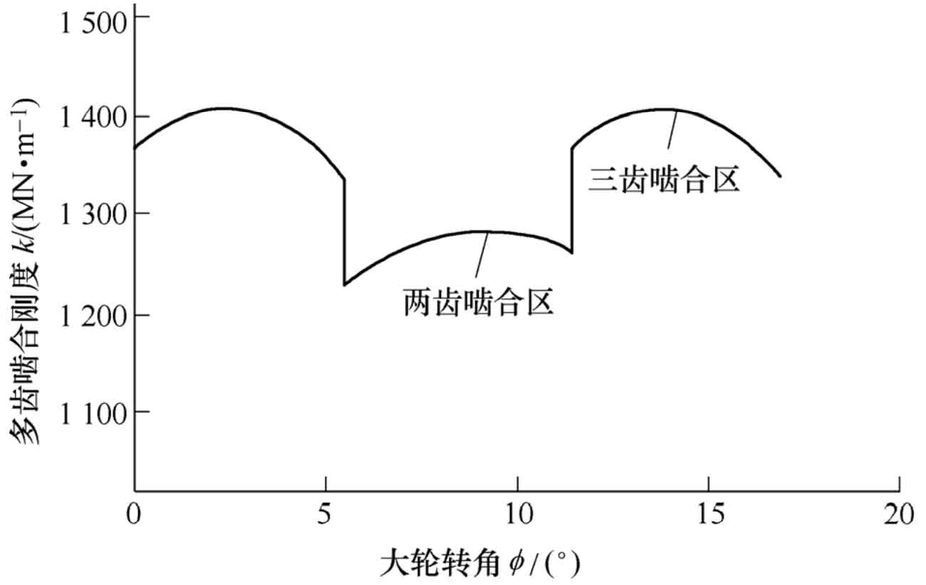
The single tooth meshing stiffness of each tooth is superimposed according to the formula to obtain the multi tooth comprehensive meshing stiffness, as shown in Figure 9.
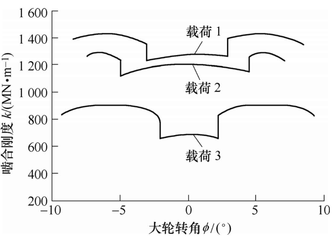
5. calculation of multi tooth meshing stiffness of spiral bevel gear under different loads
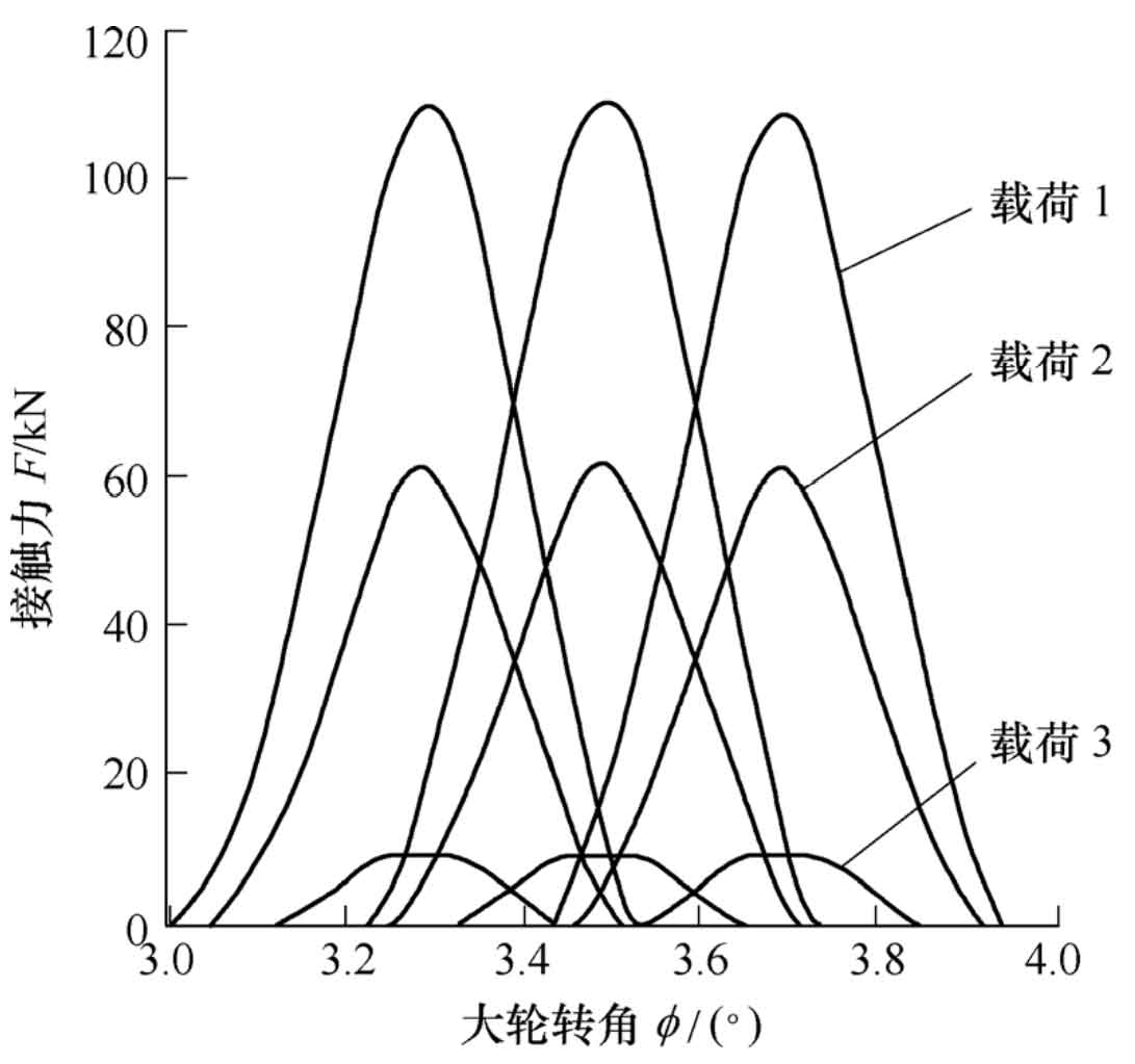
Under different loads, the contact position and coincidence degree of spiral bevel gear will change, so the stiffness curve will also change. Now, load 1 is 15 Mn · m, load 2 is 6.5 Mn · m and load 3 is 0.8 Mn · m respectively. The variation curves of contact force with time under different working conditions are obtained, as shown in FIG. 10.
Thus, the coincidence degrees under various working conditions are 2.524 0, 2.238 1 and 1.650 0. The stiffness curve under various working conditions can be calculated, as shown in Figure 11.