
The reliable operation of rotating machinery across industries, from automotive transmissions to heavy industrial equipment and aerospace systems, is fundamentally dependent on the integrity of its gear components. Among these, the spur and pinion gear configuration is ubiquitous due to its design simplicity, high efficiency in power transfer, and ease of manufacturing. However, these spur and pinion gears are subjected to severe cyclic contact and bending stresses during meshing. This repetitive loading often initiates fatigue cracks at the tooth root fillet region—a primary stress concentration zone. The propagation of these cracks can lead to catastrophic gear failures, resulting in unplanned downtime, significant economic losses, and potential safety hazards. Consequently, developing a profound understanding of the crack propagation behavior in spur and pinion gears is not merely an academic exercise but a critical engineering necessity for predictive maintenance and robust design.
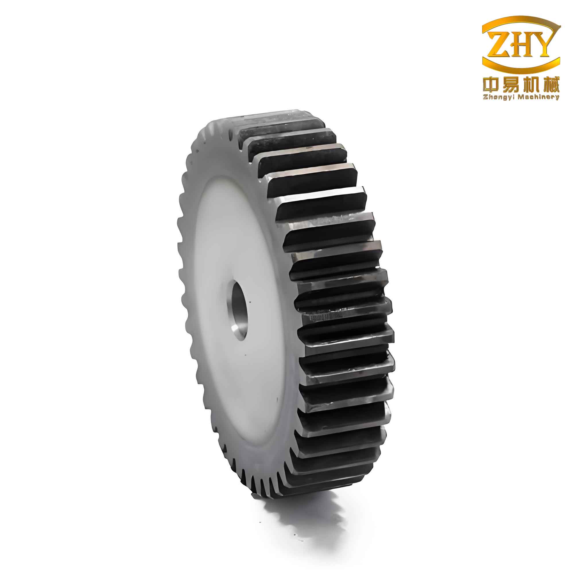
Predicting the exact path a crack will take as it grows within a spur and pinion gear tooth is a complex fracture mechanics problem. The crack tip region exhibits a singular stress field, and the path is influenced by a multitude of factors including the initial flaw location, the dynamic meshing loads, and the complex geometry of the gear body itself, such as the web structure. Traditional finite element methods (FEM) face significant challenges in modeling such evolving discontinuities, as they require constant and computationally expensive re-meshing around the advancing crack front. This work presents a comprehensive methodology based on a modified eXtended Finite Element Method (XFEM) to efficiently and accurately simulate fatigue crack propagation in spur and pinion gears. We will delve into the theoretical underpinnings, validate the model, and systematically analyze the influence of key geometric factors on the crack trajectory.
Theoretical Foundation for Crack Propagation Analysis
Stress Field at the Crack Tip
In a spur and pinion gear under load, a crack initiating at the root fillet is typically subjected to a combination of opening and sliding modes. This is classified as a mixed-mode (I/II) crack. Analyzing the stress state near the sharp crack tip is essential for predicting its growth direction. Using the theory of elasticity and considering the equilibrium equations, the stress components can be derived from an Airy stress function \( \phi(x,y) \):
$$
\sigma_x = \frac{\partial^2 \phi}{\partial y^2}, \quad \sigma_y = \frac{\partial^2 \phi}{\partial x^2}, \quad \tau_{xy} = -\frac{\partial^2 \phi}{\partial x \partial y}
$$
To handle the discontinuity and stress singularity at the tip of a crack in a spur and pinion gear tooth, the Westergaard stress function approach, formulated using complex variables, provides an elegant solution. For a mixed-mode crack, the stress field in the vicinity of the tip (with coordinates \( r, \theta \) originating at the tip) is given by:
$$
\begin{aligned}
\sigma_x &= \frac{K_I}{\sqrt{2\pi r}} \cos\frac{\theta}{2}\left(1 – \sin\frac{\theta}{2}\sin\frac{3\theta}{2}\right) – \frac{K_{II}}{\sqrt{2\pi r}} \sin\frac{\theta}{2}\left(2 + \cos\frac{\theta}{2}\cos\frac{3\theta}{2}\right) \\
\sigma_y &= \frac{K_I}{\sqrt{2\pi r}} \cos\frac{\theta}{2}\left(1 + \sin\frac{\theta}{2}\sin\frac{3\theta}{2}\right) + \frac{K_{II}}{\sqrt{2\pi r}} \sin\frac{\theta}{2} \cos\frac{\theta}{2} \cos\frac{3\theta}{2} \\
\tau_{xy} &= \frac{K_I}{\sqrt{2\pi r}} \cos\frac{\theta}{2} \sin\frac{\theta}{2} \cos\frac{3\theta}{2} + \frac{K_{II}}{\sqrt{2\pi r}} \cos\frac{\theta}{2}\left(1 – \sin\frac{\theta}{2}\sin\frac{3\theta}{2}\right)
\end{aligned}
$$
Here, \( K_I \) and \( K_{II} \) are the Mode I (opening) and Mode II (sliding) stress intensity factors (SIFs), respectively. These SIFs are the fundamental parameters governing the magnitude of the singular stress field around the crack in the spur and pinion gear and are functions of the applied load, crack length, and component geometry.
| Mode | Description | Driving Stress | Stress Intensity Factor (SIF) |
|---|---|---|---|
| I | Opening | Tensile stress perpendicular to crack plane | \( K_I \) |
| II | Sliding (In-plane shear) | Shear stress parallel to crack plane and perpendicular to crack front | \( K_{II} \) |
| III | Tearing (Out-of-plane shear) | Shear stress parallel to crack plane and crack front | \( K_{III} \) |
Crack Propagation Criteria
To predict the crack growth direction (\( \theta_0 \)) and the critical condition for propagation, a fracture criterion is required. The maximum circumferential (hoop) stress criterion is widely used for mixed-mode problems in brittle and quasi-brittle materials like high-strength gear steels. This theory postulates that the crack will extend in the direction where the circumferential tensile stress \( \sigma_{\theta\theta} \) is maximum. The associated SIF for this direction, \( K_{\theta} \), is derived as:
$$
K_{\theta} = \lim_{r \to 0} \sqrt{2\pi r} \, \sigma_{\theta\theta} = \cos\frac{\theta}{2} \left[ K_I \cos^2\frac{\theta}{2} – \frac{3}{2} K_{II} \sin\theta \right]
$$
The crack extension angle \( \theta_0 \) is found by solving \( \partial K_{\theta}/\partial \theta = 0 \), leading to:
$$
\theta_0 = 2 \arctan\left[ \frac{1}{4}\left( \frac{K_I}{K_{II}} \right) \pm \sqrt{ \left( \frac{K_I}{K_{II}} \right)^2 + 8 } \right]
$$
The crack is assumed to propagate when the maximum value of \( K_{\theta} \) (i.e., \( K_{\theta}(\theta_0) \)) reaches the material’s fracture toughness \( K_{IC} \). For fatigue analysis, the crack growth rate \( da/dN \) is often governed by the Paris law, which for mixed-mode conditions can be formulated in terms of an equivalent SIF range \( \Delta K_{eq} \), often related to \( \Delta K_{\theta} \).
The Modified Extended Finite Element Method (XFEM)
The standard FEM struggles with modeling growing cracks due to the need for the mesh to conform to the crack geometry. The eXtended Finite Element Method (XFEM) overcomes this by enriching the standard FEM approximation with discontinuous functions, allowing the crack to traverse through elements without re-meshing. The displacement approximation in XFEM is:
$$
\mathbf{u}(\mathbf{x}) = \underbrace{\sum_{i \in \mathcal{N}} N_i(\mathbf{x}) \mathbf{u}_i}_{\text{Standard FEM}} + \underbrace{\sum_{j \in \mathcal{N}_{cr}} N_j(\mathbf{x}) H(\mathbf{x}) \mathbf{a}_j}_{\text{Heaviside Enrichment}} + \underbrace{\sum_{k \in \mathcal{N}_{tip}} N_k(\mathbf{x}) \left( \sum_{\alpha=1}^4 F_{\alpha}(\mathbf{x}) \mathbf{b}_k^{\alpha} \right)}_{\text{Crack Tip Enrichment}}
$$
Where \( \mathcal{N} \) is the set of all nodes, \( \mathcal{N}_{cr} \) are nodes of elements cut by the crack, and \( \mathcal{N}_{tip} \) are nodes of elements containing the crack tip. \( H(\mathbf{x}) \) is a Heaviside step function representing the jump across the crack face, and \( F_{\alpha}(\mathbf{x}) \) are asymptotic functions that capture the crack tip singularity (e.g., \( \sqrt{r}\sin(\theta/2), \sqrt{r}\cos(\theta/2), … \)).
However, a direct implementation can lead to “blending elements” where only some nodes are enriched, compromising the partition of unity property and solution accuracy. The modified XFEM addresses this by employing a shifted enrichment and a ramp function \( R(\mathbf{x}) \). The enriched displacement field is corrected to:
$$
\mathbf{u}(\mathbf{x}) = \sum_{i} N_i(\mathbf{x}) \mathbf{u}_i + \sum_{j \in \mathcal{N}_{cr}} N_j(\mathbf{x}) [H(\mathbf{x}) – H(\mathbf{x}_j)] \mathbf{a}_j + \sum_{k \in \mathcal{N}_{tip}} N_k(\mathbf{x}) R(\mathbf{x}) \left( \sum_{\alpha=1}^4 [F_{\alpha}(\mathbf{x}) – F_{\alpha}(\mathbf{x}_k)] \mathbf{b}_k^{\alpha} \right)
$$
This modification ensures a smooth transition between enriched and standard elements, significantly improving the accuracy and convergence of SIF calculations for cracks in complex geometries like a spur and pinion gear.
Finite Element Model of a Spur and Pinion Gear Pair
To investigate the crack propagation behavior, a finite element model of a meshing spur and pinion gear pair was developed. The focus of the simulation is on the driving pinion, where the root crack is initiated. A sub-model containing two teeth of the pinion was extracted to reduce computational cost while capturing the essential load transfer and boundary conditions. The model incorporates a realistic gear body design including a web and web holes.
| Parameter | Symbol | Value (Pinion) | Value (Gear) |
|---|---|---|---|
| Number of Teeth | \( z \) | 28 | 28 |
| Module | \( m_n \) | 4 mm | 4 mm |
| Face Width | \( b \) | 20 mm | 20 mm |
| Web Thickness | \( B_w \) | 10 mm | – |
| Web Inner Radius | \( r_{wi} \) | 36 mm | – |
| Web Outer Radius (Variable) | \( r_{wo} \) | 40 – 48 mm | – |
| Web Hole Diameter | \( \Phi_s \) | 12 mm | – |
| Young’s Modulus | \( E \) | 210 GPa | |
| Poisson’s Ratio | \( \nu \) | 0.28 | |
| Density | \( \rho \) | 7830 kg/m³ | |
The model was discretized with approximately 6,500 high-order elements. Convergence studies were performed to ensure that the mesh density, particularly around the potential crack path and the root fillet, was sufficient to resolve the stress gradients. A key metric for mesh independence in fracture simulation is the stabilization of calculated Stress Intensity Factors (SIFs). The mesh size \( h \) near the crack tip was selected based on the relation \( h \ll \rho \), where \( \rho \) is the size of the plastic zone or process zone. For linear elastic analysis, a common rule is:
$$
h \le \frac{1}{4} \left( \frac{K_I}{\sigma_{ys}} \right)^2
$$
where \( \sigma_{ys} \) is the material yield strength. Boundary conditions were applied to simulate a static load equivalent to the peak meshing force during single-tooth contact. The pinion shaft was fixed, and equivalent forces representing the transmitted torque were applied at the tooth tip of the loaded flank: a tangential force \( F_t = -3,385.82 \, \text{N} \) and a radial force \( F_r = -1,232.34 \, \text{N} \). Five distinct initial crack nucleation sites were defined along the tension-side root fillet of the critical tooth, labeled Position 1 (closest to the loaded flank) to Position 5 (furthest away). Each initial flaw was modeled as a small crack of length \( a_0 = 0.5 \, \text{mm} \).
Analysis of Influencing Factors on Crack Path
Using the validated modified XFEM model, a series of parametric studies were conducted to isolate and understand the effect of three critical factors on the crack propagation path within the spur and pinion gear.
Effect of Initial Crack Nucleation Point
The location where a fatigue crack initiates on the root fillet of a spur and pinion gear tooth is stochastic but greatly influences the subsequent failure mode. Simulations were run for initial cracks at the five predefined positions.
Observations: Cracks initiating closer to the loaded flank (Position 1) exhibited a path that curved sharply towards the gear’s rim and then propagated almost parallel to it, leading to a traditional rim fracture. Cracks initiating further away from the loaded flank (Positions 4 & 5) showed a more pronounced initial trajectory into the gear body/web before turning. The crack from Position 3, centrally located, followed a path that was a balance between these two tendencies. The fundamental reason is the gradient of the principal stress field at the root. The initial growth direction, governed by the local \( K_I/K_{II} \) ratio, seeks the path of maximum energy release rate or maximum hoop stress, which changes as the crack extends and interacts with the global stress field of the loaded spur and pinion gear.
| Nucleation Point | Initial \( K_I \) (MPa√m) | Initial \( K_{II} \) (MPa√m) | Initial \( K_I/K_{II} \) Ratio | Dominant Failure Mode Trajectory |
|---|---|---|---|---|
| Position 1 | ~27.5 | ~4.8 | ~5.73 | Sharp turn towards rim, rim fracture |
| Position 2 | – | – | – | Moderate curvature, rim fracture |
| Position 3 | ~30.4 | ~7.4 | ~4.11 | Balanced path, tooth/rim fracture |
| Position 4 | – | – | – | Path into web, tooth fracture |
| Position 5 | ~36.0 | ~9.9 | ~3.64 | Significant path into web, large tooth fracture |
Effect of Web Outer Diameter
The web structure connects the gear rim to the hub and its dimensions are crucial for weight and stiffness. The outer diameter of the web \( r_{wo} \) was varied from 40 mm to 48 mm to study its effect on crack path deviation for a crack starting at Position 3.
Observations: A clear trend was observed. As the web outer diameter increased, bringing the web structure closer to the tooth root, the crack path was systematically “attracted” towards the web. With a small web diameter (\( r_{wo} = 40 \, \text{mm} \)), the crack grew almost exclusively within the rim and tooth region. At \( r_{wo} = 46 \, \text{mm} \), the crack path showed a noticeable deflection towards the web mid-way through its propagation. At the largest diameter (\( r_{wo} = 48 \, \text{mm} \)), the crack initiated a trajectory directly into the web much earlier. This phenomenon occurs because the stiff web structure alters the global compliance and the stress field in the gear body. The propagating crack seeks the path of least resistance and higher strain energy density, which shifts as the proximity of the stiffer web changes the load paths within the spur and pinion gear body.
| Web Outer Diameter (\( r_{wo} \)) | Crack Path Characteristic | Primary Failure Region | Engineering Implication |
|---|---|---|---|
| 40 mm (Small) | Path remains near rim/tooth root | Rim/Tooth Breakage | Traditional failure, easier to detect via vibration. |
| 42 mm | Slight deflection observable | Transition Zone | Potential for larger fracture surface. |
| 46 mm | Clear deflection towards web | Web/Rim Junction | Risk of catastrophic web failure, higher stress concentration. |
| 48 mm (Large) | Early and significant path into web | Web Structure | High risk of sudden, complete gear failure. |
Effect of Web Hole Proximity and Angular Position
Lightening holes in the gear web are common. Their presence creates additional stress concentrators that can interact with a growing crack. Simulations were performed with a web hole of fixed diameter (12 mm) but with its angular position \( \theta_P \) relative to the crack nucleation point varied from -30° to +30°.
Observations: The web hole exerts a significant local perturbation on the crack path. When the hole was positioned “ahead” of the crack’s natural trajectory (\( \theta_P = +15°, +30° \)), it acted as a strong attractor, causing the crack to bend sharply towards it. When the hole was positioned “behind” the natural path (\( \theta_P = -15°, -30° \)), its influence was minimal. A hole directly in line (\( \theta_P = 0° \)) caused a moderate deflection. This can be quantified using a “Path Deviation Factor” \( D \), defined as the distance between the actual crack path and the predicted path without a hole at a specific reference length. The interaction is governed by the principle of mutual competition between stress concentrators. The crack tip, being a potent stress concentrator itself, is drawn towards the hole because linking with this other discontinuity allows the system to relax more strain energy than continuing through homogeneous material. This is a critical finding for the design of lightweight spur and pinion gears, indicating that web holes must be carefully positioned away from the projected high-stress zones of the tooth roots.
| Hole Angle \( \theta_P \) | Relative Position to Natural Crack Path | Crack Path Interaction | Qualitative Strength of Attraction |
|---|---|---|---|
| -30° | Behind / Below | Negligible to very weak deflection | Very Low |
| -15° | Slightly Behind | Weak or no observable deflection | Low |
| 0° | In-line / Directly Ahead | Moderate deflection towards the hole | Medium |
| +15° | Ahead and Lateral | Strong deflection and curvature towards the hole | High |
| +30° | Significantly Ahead and Lateral | Very strong, early-stage deflection towards the hole | Very High |
Conclusions and Engineering Significance
This investigation has successfully demonstrated the application of a modified XFEM framework for simulating mixed-mode fatigue crack propagation in spur and pinion gears. The method effectively handles the crack tip singularity and path evolution without re-meshing, providing an efficient and accurate tool for failure analysis. The parametric studies yield several crucial insights for the design and health management of spur and pinion gears:
- Crack Initiation Location is Paramount: The specific point of crack nucleation on the tooth root fillet predetermines the subsequent failure mode—be it a clean rim fracture or a more complex fracture propagating into the gear body. This underscores the importance of precise manufacturing and surface treatment of the root fillet in spur and pinion gears to minimize initiation sites.
- Web Geometry is a Key Design Parameter for Durability: The size and placement of the web are not merely weight-saving considerations. An oversized web outer diameter can dangerously alter crack paths, potentially leading to sudden and catastrophic web failures instead of more predictable tooth or rim failures. Design optimization must balance stiffness, weight, and fail-safe behavior.
- Web Holes Can Act as Crack Magnets: Lightening holes must be positioned with extreme caution. Their presence in the trajectory zone of a potential root crack can drastically accelerate failure by providing a low-energy path for crack coalescence. A detailed fracture mechanics assessment should accompany the placement of such holes in highly stressed spur and pinion gears.
The integration of this advanced simulation capability into the gear design process allows for a more proactive approach to durability. It enables engineers to perform virtual “what-if” scenarios, evaluating the fracture resistance of different spur and pinion gear geometries and identifying potential weak points before physical prototyping. Furthermore, this understanding aids in developing more targeted condition monitoring strategies by predicting the likely crack paths and associated changes in mesh stiffness and vibration signatures. Ultimately, mastering the analysis of crack propagation empowers the creation of safer, more reliable, and longer-lasting spur and pinion gear transmissions.