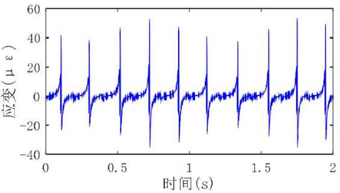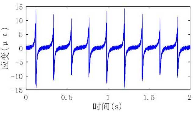
The dynamic strain of tooth root measured by fiber Bragg grating sensor and piezoelectric strain sensor is analyzed. The dynamic strain of tooth root measured by fiber Bragg grating sensor and piezoelectric strain sensor is shown in Fig. 1 and Fig. 2 respectively. The strain pulse change measured by strain sensor within 2S is shown in the figure. At this time, the driving and driven gears in the gearbox are healthy gears, and the input speed of the gearbox is 500 rpm, The output torque of the driven gear is 500 nm, which represents one rotation cycle of the driven gear. Compared with the strain measurement results of the two sensors, the strain signals measured by the fiber Bragg grating sensor and the piezoelectric strain sensor have the same change mode; it is worth noting that the strain signal amplitude measured by the piezoelectric sensor is smaller than that measured by the fiber Bragg grating strain signal. This may be due to the fact that the length of the piezoelectric strain sensor (15mm) is much larger than that of the FBG sensor (5mm), which will lead to a larger measurement contact area of the sensor, thus reducing the average value of strain. However, the average value of fiber Bragg grating strain amplitude actually measured, if converted into stress according to Hooke’s law, is about 9Mpa, which is still far less than the stress calculated according to formula (4-6) (about 23mpa). The reasons for the above phenomena may be: firstly, the fiber Bragg grating sensor is not accurately installed on the dangerous section of the gear tooth with the largest strain; secondly, the strain on the end face of the gear tooth is less than the actual strain of the gear tooth; in addition, the fiber Bragg grating sensor measures the average stress within the grating length range (5mm), which further leads to the reduction of the measured strain.

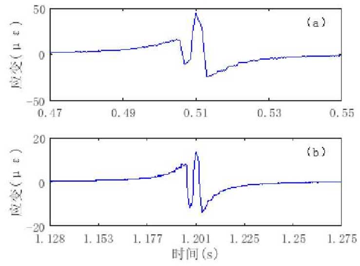
In order to more clearly observe the change process of gear tooth root strain under the running state of gear, Fig. 3 shows the local enlarged diagram of strain measured by two kinds of sensors respectively. It is found that the strain signals measured by the two sensors have the same change trend. During the meshing process of each gear tooth, the strain sensor is stretched first and then compressed (the strain is positive when stretching and negative when compressing), and then it is stretched and then compressed again. Similar experimental phenomena are also given. The possible explanation of the above phenomenon: Hypothesis 2 When the measured tooth is close to the meshing position, the adjacent tooth will produce tensile strain in the meshing area, which will affect the strain of the measured tooth, which explains that the tensile strain at the root of the tooth increases gradually first; when the measured tooth enters into the meshing, another tooth is still engaged, which is the double tooth meshing area The stress of the measured tooth in the meshing area is compressive stress; as the measured tooth enters into the single tooth meshing area, the stress of the measured tooth will increase, and the tensile strain plays a leading role in the single tooth meshing area, and the tensile strain reaches the maximum value; with the meshing of the measured tooth, the tensile stress continuously decreases and gradually changes to the compressive stress, and when the measured tooth withdraws from meshing, the compressive stress decreases gradually Small to zero.

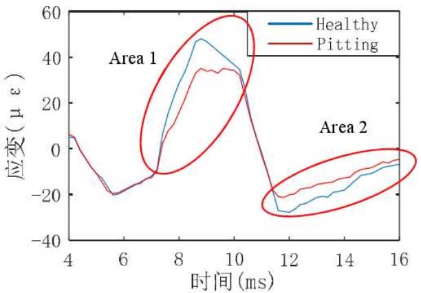
By comparing the dynamic strain measured by fiber Bragg grating sensor and piezoelectric strain sensor, the feasibility of using fiber Bragg grating sensor to measure gear root strain is proved. Therefore, in the gear root dynamic strain measurement experiment, the light grating sensor is used to measure the dynamic bending strain of the healthy gear and the gear with moderate pitting fault degree. Fig. 4 shows the dynamic bending strain of the healthy gear and the gear with medium range pitting fault under the input speed of 500rpm and the output torque of 500nm. It can be clearly seen that pitting on the gear tooth surface will lead to the reduction of gear bending strain. For example, the strain in area 1 decreases significantly from the middle of double tooth meshing area to the end of single tooth meshing area, and the compressive stress in area 2 area also decreases slightly. The above results show that the tooth surface pitting will lead to a significant reduction of gear root strain, which also indicates that the tooth with pitting fault will provide smaller torque for gear meshing.

