

1. Introduction
- Research Background: Understanding the time-varying meshing parameters of hypoid gear pairs under loaded conditions is crucial for accurately describing internal excitation in dynamic models and evaluating dynamic meshing characteristics. However, existing methods for calculating meshing parameters have limitations.
- Research Objectives: This paper aims to conduct a loaded tooth contact analysis (LTCA) of hypoid gear pairs under different loads, extract and calculate parameters such as real tooth deformation and meshing stiffness, and analyze the evolution of meshing parameters with load changes.
2. Mathematical Description of Time-Varying Meshing Parameters
2.1 Equivalent Meshing Force
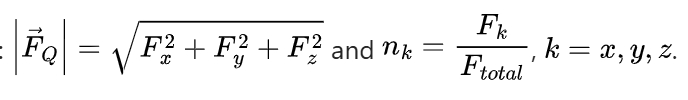
- Definition: The equivalent meshing force
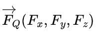
is the resultant vector of the instantaneous equivalent meshing forces on all contact tooth surfaces at a certain moment. Its components along the x, y, and z axes are calculated as
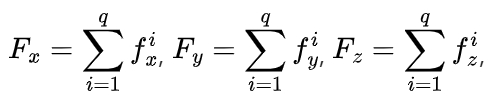
where q is the number of instantaneous contact tooth pairs, and

is the equivalent meshing force vector on the i-th contact tooth surface.
- Formula:
2.2 Equivalent Meshing Point
- Definition: The equivalent meshing point is the point of action of the resultant force of the equivalent meshing forces on all meshing tooth surfaces at a certain moment, obtained based on the force balance relationship.
- Calculation Formula:
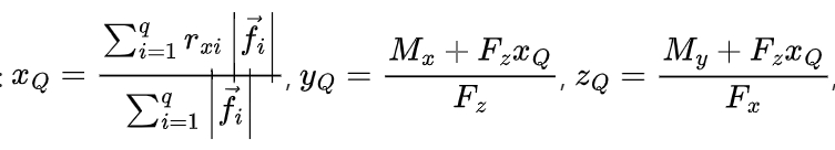
where rxi is the x-component of the radius vector of the equivalent meshing force action point on the i-th contact tooth surface, and Mx and My are the torques of FQ around the x and y axes of the meshing coordinate system.
2.3 Transmission Error Function
- Definition: The transmission error of a hypoid gear pair is defined as the difference between the actual and theoretical rotation angles of the large gear when the small gear rotates at a constant speed.
- Formula:
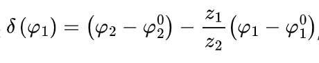
where z1 and z2 are the numbers of teeth of the small and large gears, respectively, and φ01 and φ02 are the initial rotation angles of the small and large gears at the reference point meshing.
2.4 Tooth Comprehensive Elastic Deformation
- Components: The comprehensive elastic deformation of a tooth includes contact deformation , bending deformation , and shear deformation .
- Calculation Method: The comprehensive elastic deformation of the gear pair can be obtained by calculating the combined deformation of the three types of deformation at the contact points of the large and small gear tooth surfaces. The actual displacement of the tooth during dynamic meshing is the sum of the comprehensive elastic deformation and the rotational displacement.
2.5 Time-Varying Meshing Stiffness
- Definition: The meshing stiffness of the gear pair at time is defined as the ratio of the equivalent meshing force to the comprehensive elastic deformation at that time.
- Formula: .
3. LTCA Analysis
3.1 Gear Pair Design and Machining Parameters
- Gear Pair Geometry Parameters (Table 1):
| Parameter | Value (Small Gear) | Value (Large Gear) |
|---|---|---|
| Helix Direction | Left-handed | Right-handed |
| Number of Teeth | 10 | 41 |
| Module (mm) | 4.741 | – |
| Shaft Angle (°) | 90 | – |
| Offset Distance (mm) | -31.8 (Small gear lower offset) | – |
| Tooth Face Width (mm) | 33.637 | 28 |
| Outer Cone Distance (mm) | 117.178 | 101.26 |
| Helix Angle (°) | 49.983 | 29.000 |
| Pitch Cone Angle (°) | 15.529 | 73.700 |
| Face Cone Angle (°) | 20.533 | 74.873 |
| Root Cone Angle (°) | 14.183 | 68.133 |
| Outer End Addendum Height (mm) | 7.27 | 1.47 |
| Outer End Theoretical Dedendum Height (mm) | 2.69 | 8.26 |
| Working Tooth Height (mm) | 8.63 | – |
| Distance of Pitch Cone Vertex beyond Shaft Intersection Point (mm) | 18.11 | -3.05 |
| Distance of Face Cone Vertex beyond Shaft Intersection Point (mm) | 11.80 | -3.60 |
| Distance of Root Cone Vertex beyond Shaft Intersection Point (mm) | 21.52 | -1.36 |
- Large Gear Machining Parameters (Table 2):
| Parameter | Value |
|---|---|
| Nominal Diameter of Cutter Head (inch) | 7.5 |
| Tooth Profile Angle of Outer Cutter Tooth (°) | -24 |
| Tooth Profile Angle of Inner Cutter Tooth (°) | 17 |
| Cutter Tip Offset Distance (mm) | 2.286 |
| Cutter Tip Fillet Radius (mm) | 1.016 |
| Machine Tool Installation Root Cone Angle (°) | 68.133 |
| Horizontal Cutter Position (mm) | 41.110 |
| Vertical Cutter Position (mm) | 83.660 |
| Axial Wheel Position (mm) | -1.360 |
| Vertical Wheel Position (mm) | 0 |
- Small Gear Machining Parameters (Table 3):
| Parameter | Value (Concave Surface – Outer Cutter) | Value (Convex Surface – Inner Cutter) |
|---|---|---|
| Cutter Tooth Profile Angle (°) | 14 | -31 |
| Cutter Tip Radius | 92.456 | 97.917 |
| Cutter Tip Fillet Radius (mm) | 0.0635 | 0.0635 |
| Machine Tool Installation Root Cone Angle (°) | -4.3 | -4.316667 |
| Radial Cutter Position (mm) | 89.8950 | 93.5458 |
| Angular Cutter Position (°) | 87.1750 | 82.0249 |
| Axial Wheel Position (mm) | -2.33 | 2.60 |
| Vertical Wheel Position (mm) | 29.87 | 32.52 |
| Bed Position (mm) | 11.99 | 20.80 |
| Cutter Tilt Angle (°) | 21.2513 | 18.8262 |
| Cutter Rotation Angle (°) | -19.6319 | -34.2973 |
| Cutting Rolling Ratio | 3.87250 | 4.03515 |
3.2 Finite Element Model Construction
- Model Generation: Based on the meshing and machining principles of the hypoid gear pair, the coordinates of the gear tooth surface points are calculated, and a three-dimensional model of the gear pair is established. The small gear with all teeth and 18 teeth of the large gear (total number of teeth is 41) are selected for analysis. The tooth surface contact force is highly concentrated near the contact area, and the grid of the tooth surface and root is encrypted using the substructure method, while the rest is sparsified.
3.3 Pre- and Post-Processing Settings
- Pre-Processing: The LTCA calculation pre-processing includes setting the analysis type, material parameters, element attributes, boundary conditions, load application, and output variables. The elastic modulus is set to MPa, the density is kg/m³, the Poisson’s ratio is 0.3, and the friction coefficient is 0.1. The contact property is set to “Hard Contact”, and the element type is C3D8R. The analysis type is implicit and static. The simulation step size is 0.005 mm, and geometric nonlinearity is enabled. The slip type is set to “Finite Sliding”, and variables such as CNORMF, CFNM, CMNM, CNAREA, UR, COORD, CSTATUS, and CFORCE are output. The number of elements for the small gear is 124800, and for the large gear is 201600.
- Boundary Conditions and Load Application: Reference points are established at the centers of the large and small gears and rigidly coupled with the nodes of the gear inner holes. The load and boundary conditions are applied at the center reference points. The entire meshing process is divided into three load steps to ensure convergence. In the first step, the relative positions of the gears are adjusted to create an appropriate tooth side clearance. In the second step, a small axial rotation angle is applied to the small gear to make the tooth surfaces contact and eliminate the clearance. In the third step, the gears are driven by applying a constant axial rotational speed to the small gear and a constant axial negative load torque to the large gear.
4. LTCA Example Analysis
4.1 Meshing Mark Comparison
- Verification Method: The LTCA calculation results are verified by comparing the tooth surface marks obtained from the LTCA with those from the loaded contact test.
- Comparison Result: The simulation results of the instantaneous contact area on the large gear tooth surface obtained by LTCA are in good agreement with the marks obtained from the loaded test, confirming the correctness of the LTCA analysis.
4.2 Equivalent Meshing Point
- Position: The position of the equivalent meshing point during the meshing process is shown in Figure 5. Due to modeling and simulation errors, the equivalent meshing point is located within a small spatial plane range.
4.3 Time-Varying Meshing Parameters
- Equivalent Meshing Force: The equivalent meshing force of the gear pair under the 4000 N・m load torque and 200 r/min driving speed condition is shown in Figure 6 (a). It varies periodically with the rotation of the gears and has no significant .
- Bearing Transmission Error: The bearing transmission error of the gear pair is shown in Figure 6(b). It also varies periodically and shows a trend of first decreasing and then increasing with the increase in load.
- Comprehensive Elastic Deformation: The comprehensive elastic deformation of the gear pair is shown in Figure 6(c). It varies periodically and increases with the increase in load.
- Meshing Stiffness: The meshing stiffness of the gear pair is shown in Figure 6(d). It varies periodically with the rotation of the gears, and the shape of the stiffness curve changes significantly with different loads. The peak of the curve shifts forward with the increase in load and is asymmetric about the peak.
5. Evolution Analysis of Meshing Parameters
5.1 Tooth Surface Contact Area
- Change with Load: The tooth surface contact area gradually expands from the middle of the tooth surface to the entire tooth surface with the increase in load, and the starting meshing position gradually moves towards the large end.
5.2 Equivalent Meshing Force
- Relationship with Load: The change ratio of the equivalent meshing force is approximately consistent with the change in the load torque. It varies periodically with the same frequency as the gear pair meshing frequency.
5.3 Bearing Transmission Error
- Evolution Trend: At low loads, the transmission error decreases with the increase in load until it reaches the ideal contact area, and then increases with further load increase. The overall trend is “first decreasing and then increasing”.
5.4 Tooth Surface Contact Force and Actual Contact Ratio
- Tooth Surface Contact Force: The single-tooth contact force of the hypoid gear pair increases with the increase in load.
- Actual Contact Ratio: The actual contact ratio increases rapidly at low loads and then becomes relatively stable as the load continues to increase.
5.5 Comprehensive Elastic Deformation and Time-Varying Meshing Stiffness
- Comprehensive Elastic Deformation: The amount and fluctuation amplitude of the comprehensive elastic deformation of the hypoid gear pair increase with the increase in load.
- Time-Varying Meshing Stiffness: The meshing stiffness curve varies periodically with the same frequency as the gear pair meshing frequency. The shape of the curve changes significantly with different loads, and the peak shifts forward with the increase in load and is asymmetric.
6. Conclusions
- The equivalent meshing force, bearing transmission error, comprehensive elastic deformation, and time-varying meshing stiffness of the hypoid gear pair vary periodically with the rotation of the gears and have no significant . The meshing mark on the tooth surface expands from the middle to the entire tooth surface with the increase in load, and the starting meshing position moves towards the large end.
- The actual contact ratio of the hypoid gear pair increases nonlinearly with the increase in load. At low loads, the change in the contact ratio is significant, and the load distribution and dynamic load of the teeth should be considered in dynamic analysis.
- The meshing deformation and its fluctuation amplitude of the hypoid gear pair increase with the increase in load. The peak of the meshing stiffness curve shifts forward and becomes asymmetric with the increase in load. The fluctuation amplitude of the transmission error first increases and then decreases with the increase in load, and there is a load range with a relatively small fluctuation amplitude. It is necessary to accurately describe the meshing stiffness and transmission error in the dynamic analysis of the hypoid gear system.