
In the field of precision gear manufacturing, especially for spiral bevel gears used in automotive, aerospace, and industrial machinery, the accuracy of gear milling processes is paramount. As an engineer specializing in CNC machine tool design, I have extensively studied the transmission chain of the workhead in CNC spiral bevel gear milling machines. This analysis focuses on controlling gear accuracy, particularly backlash, to ensure high-quality gear milling outcomes. Gear milling involves cutting teeth into gears with high precision, and any inaccuracies in the transmission system can lead to deviations in tooth profile, pitch errors, and surface roughness, ultimately affecting gear performance and longevity.
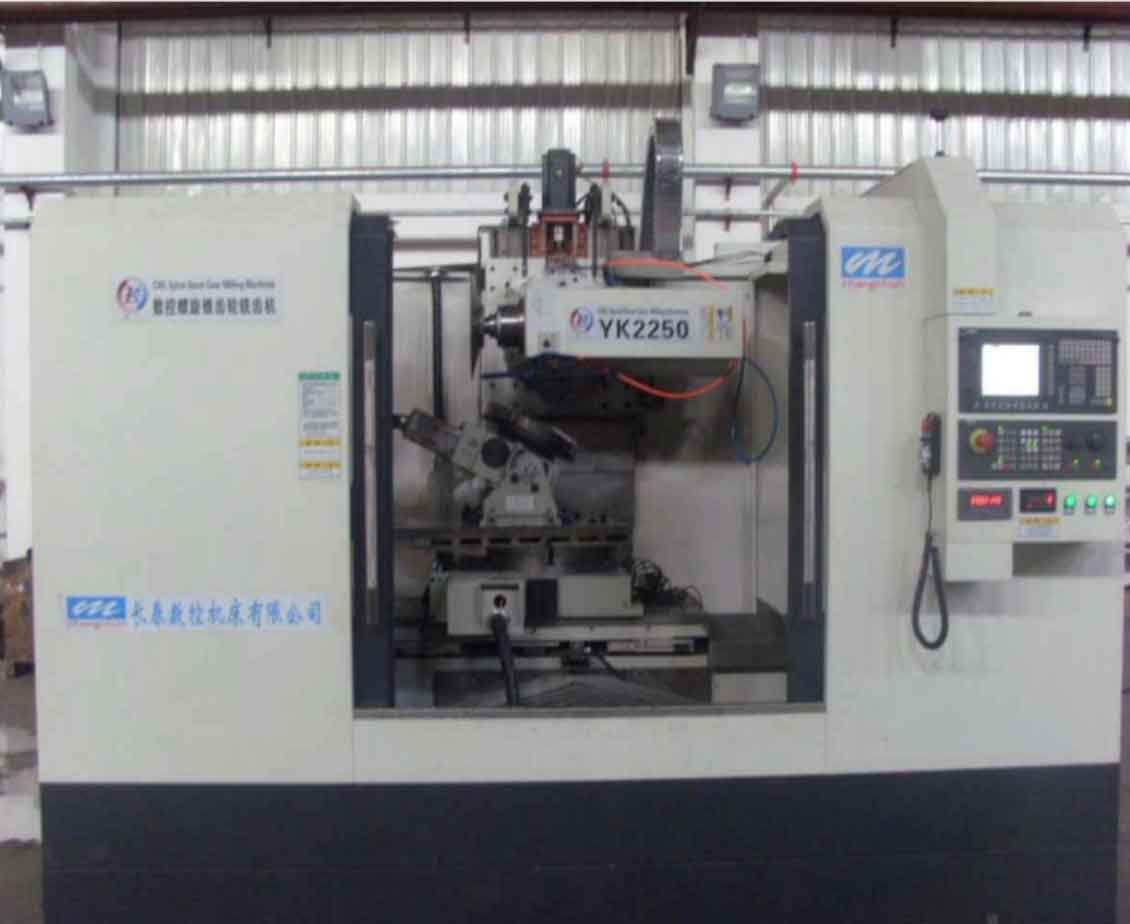
The CNC spiral bevel gear milling machine is a complex system with multiple axes of control, typically six axes for five or six-axis联动 to produce arc-shaped or cycloidal teeth. The workhead, which holds the workpiece gear, is driven by a servo motor through a gear transmission chain. This chain’s precision directly influences the indexing accuracy during gear milling, impacting the final gear’s齿距偏差 (pitch deviation) and surface finish. In my design experience, I have found that traditional machines often use worm gear pairs at the end of the transmission chain for high reduction ratios and self-locking properties. However, modern high-speed gear milling for摆线齿 (cycloidal teeth) requires higher spindle speeds, making worm gears less suitable. Instead, precision gear pairs are employed, which demand stricter control of backlash and other accuracy parameters.
Gear backlash, defined as the clearance between mating teeth, is a critical factor in transmission accuracy. During gear milling, excessive backlash can cause positional errors in the workpiece spindle, leading to inaccuracies in tooth formation. This is particularly problematic in semi-closed-loop control systems, where the servo motor cannot compensate for deviations within the backlash range. Even in closed-loop systems with feedback from圆光栅 (rotary encoders), backlash-induced lags can result in加工误差 (machining errors). In my analysis, I quantify backlash effects using mathematical models. For a gear pair, the total backlash \( B_{\text{total}} \) can be expressed as the sum of various error contributions:
$$ B_{\text{total}} = B_{\text{base}} + \Delta B_{\text{centerdistance}} + \Delta B_{\text{runout}} + \Delta B_{\text{profile}} + \Delta B_{\text{key}} $$
Here, \( B_{\text{base}} \) is the inherent backlash from gear tooth thinning, \( \Delta B_{\text{centerdistance}} \) is due to center distance variations, \( \Delta B_{\text{runout}} \) from gear runout, \( \Delta B_{\text{profile}} \) from tooth profile errors, and \( \Delta B_{\text{key}} \) from keyway配合间隙 (fitting backlash). Each component must be minimized through design and manufacturing controls. For gear milling applications, I target a maximum backlash of 20 μm for the final gear pair, similar to traditional worm gear setups, but with tighter controls on preceding stages due to reduced reduction ratios.
The workhead transmission chain in my design consists of multiple gear stages, with varying传动比 (transmission ratios) such as 9.06, 27.11, 45.05, and 87.11, achieved through交换齿轮 (change gears). Each stage’s gear accuracy is critical, as errors propagate through the chain. I specify gear精度等级 (accuracy grades) according to ISO standards: Grade 4 for the final pair and Grade 5 for preceding pairs. To control backlash, I adjust公法线长度 (base tangent length) deviations and tolerances. The公法线长度上偏差 (upper deviation of base tangent length) for a gear pair, denoted as \( \sum E \), is determined based on minimum required backlash and other error factors. The formula is:
$$ \sum E = E_1 + E_4 + E_5 + E_6 + 0.5 \times (E_2 + E_3 + E_7 + E_8 + E_9) $$
Where \( E_1 \) to \( E_9 \) represent error contributions from gear runout, tooth direction, tooth profile, center distance,安装同轴度 (installation coaxiality), etc. By customizing \( \sum E \) instead of using standard values, I reduce maximum backlash significantly. For example, for a Grade 5 gear pair with模数 (module) of 4 mm, the standard \( \sum E \) might be 73 μm, but my design calculates it as 33-35 μm, cutting backlash by over 50%. This meticulous control is essential for precision gear milling.
In addition to gear design, the配合间隙 between keyways and keys in change gears is a major source of backlash. Traditional designs use loose fits for ease of assembly, but this can amplify backlash when scaled to gear diameters. In my approach, I tighten tolerances: key width is controlled to 0 to -5 μm, keyway width to -40 to -83 μm after heat treatment, resulting in a maximum间隙 (clearance) of 8 μm. This is critical because, when折算到齿轮上 (converted to gear backlash), a small key clearance can magnify into significant errors. For instance, with a轴径 (shaft diameter) of 50 mm and a gear分度圆直径 (pitch diameter) of 348 mm, the amplification factor is approximately 9, so 8 μm clearance becomes 72 μm gear backlash. By reducing this, I ensure that key-related backlash does not dominate overall transmission inaccuracies during gear milling.
To illustrate the backlash control across transmission stages, I present a detailed table summarizing parameters for each gear pair. This includes传动比, gear精度等级,模数,最小侧隙 (minimum backlash), and error contributions. The data is based on my design calculations and manufacturing feasibility studies.
| Stage Level | Transmission Ratio | Gear Accuracy Grade | Module (mm) | Minimum Backlash (μm) | Error Contributions (μm) | Maximum Backlash (μm) | Backlash Converted to Final Stage (μm) |
|---|---|---|---|---|---|---|---|
| Final Stage | 9.06 | 4 | 4 | 0 | Runout: 9, Tooth Direction: 10, Profile: 0, Center Distance: 0 | 23 (21 after adjustment) | 23 (21) |
| First Preceding Stage | 9.06 | 5 | 4 | 0 | Runout: 16, Tooth Direction: 10, Profile: 8, Center Distance: 30 | 84 (71 after adjustment) | 34 (26) |
| First Preceding Stage | 27.11 | 5 | 4 | 0 | Runout: 16, Tooth Direction: 10, Profile: 8, Center Distance: 30 | 82 (62 after adjustment) | 25 (19) |
| Second Preceding Stage | 45.05 | 5 | 2 | 0 | Runout: 16, Tooth Direction: 10, Profile: 8, Center Distance: 30 | 81 (61 after adjustment) | 9 (7) |
| Second Preceding Stage | 87.11 | 5 | 2 | 0 | Runout: 16, Tooth Direction: 10, Profile: 8, Center Distance: 30 | 81 (61 after adjustment) | 8 (6) |
The table shows that after applying backlash reduction measures, the maximum backlash at the final stage is controlled to 23 μm, meeting design targets. However, preceding stages contribute additional backlash when converted to the final stage, with totals ranging from 68 μm to 84 μm for different transmission ratios. This highlights the importance of minimizing errors at every stage for high-precision gear milling. I also analyze keyway backlash separately, as it can be a significant factor. The following table summarizes keyway配合间隙 and its impact on gear backlash.
| Stage Level | Transmission Ratio | Key Clearance on Shaft (μm) | Gear Pitch Diameter (mm) | Backlash Converted to Gear (μm) | Backlash Converted to Final Stage (μm) |
|---|---|---|---|---|---|
| Final Stage | 9.06 | 0 (过盈配合) | 604 | 0 | 0 |
| First Preceding Stage | 9.06 | 8 | 254 | 41 | 27 (24) |
| First Preceding Stage | 27.11 | 8 | 345 | 55 | 20 (18) |
| Second Preceding Stage | 45.05 | 8 | 178 | 29 | 6 (5) |
| Second Preceding Stage | 87.11 | 8 | 220 | 36 | 5 (4) |
Combining gear and keyway backlash, the total converted backlash at the final stage ranges from 68 μm to 84 μm for different传动比, which is 2-3 times the final stage’s own backlash. While this exceeds ideal targets, it is acceptable given manufacturing constraints, and further reductions would require costly precision enhancements. To optimize gear milling accuracy, I also consider公法线长度允差 (base tangent length tolerance). For Grade 5 gears, the standard tolerance sum is 66-67 μm, but I allocate 33 μm per pair, distributed based on pitch diameter. This tight control ensures consistent tooth thickness during gear milling operations.
Mathematically, the relationship between公法线长度 deviation and backlash can be modeled. For a gear with number of teeth \( z \), module \( m \), and压力角 (pressure angle) \( \alpha \), the base tangent length \( W_k \) for spanning \( k \) teeth is given by:
$$ W_k = m \cos \alpha \left[ \pi (k – 0.5) + z \cdot \text{inv} \alpha \right] + 2x m \sin \alpha $$
Where \( x \) is the变位系数 (profile shift coefficient), and \( \text{inv} \alpha = \tan \alpha – \alpha \) is the involute function. The deviation \( \Delta W_k \) directly affects backlash. In practice, I set upper and lower limits for \( W_k \) to control minimum and maximum backlash. For instance, for a gear pair with \( z_1 = 26 \), \( z_2 = 151 \), \( m = 4 \) mm, \( \alpha = 20^\circ \), and \( k = 4 \), I calculate \( W_k \) and then apply deviations based on required backlash. This analytical approach is integral to precision gear milling design.
Furthermore, I implement design features to mitigate backlash. For the final stage, the主动轮 (driving gear) is integrated as a shaft gear to eliminate assembly errors, and the被动齿轮 (driven gear) is mounted on the workpiece spindle with a tapered fit and key connection using过盈配合 (interference fit) for zero clearance. The center distance is adjustable, allowing compensation for manufacturing tolerances. These measures are crucial for maintaining accuracy during high-speed gear milling, where dynamic forces can exacerbate backlash effects.
In terms of transmission chain dynamics, the overall传动精度 (transmission accuracy) is influenced by the cumulative effect of each stage. The total angular error \( \theta_{\text{total}} \) at the workpiece spindle can be expressed as:
$$ \theta_{\text{total}} = \sum_{i=1}^{n} \frac{\theta_i}{R_i} $$
Where \( \theta_i \) is the error at stage \( i \), and \( R_i \) is the reduction ratio from that stage to the final output. For a chain with three stages (final, first preceding, second preceding), and assuming backlash as the primary error, we have:
$$ \theta_{\text{total}} = \frac{B_f}{r_f} + \frac{B_1}{r_1 R_f} + \frac{B_2}{r_2 R_1 R_f} $$
Here, \( B_f, B_1, B_2 \) are backlashes at final, first, and second stages, \( r_f, r_1, r_2 \) are pitch radii, and \( R_f, R_1 \) are reduction ratios. Using values from my design, with \( B_f = 23 \) μm, \( B_1 = 84 \) μm, \( B_2 = 81 \) μm, \( r_f = 302 \) mm (for pitch diameter 604 mm), \( r_1 = 127 \) mm, \( r_2 = 89 \) mm, \( R_f = 9.06 \), \( R_1 = 5.80 \), I compute \( \theta_{\text{total}} \) to validate accuracy. This model helps optimize stage designs for minimal error propagation in gear milling processes.
Additionally, I consider thermal and load effects during gear milling. Under cutting forces, gears may deflect, increasing effective backlash. I use finite element analysis to simulate deformations and adjust tolerances accordingly. For example, for a gear pair transmitting torque \( T \), the tooth deflection \( \delta \) can be estimated using:
$$ \delta = \frac{F_t}{k} $$
Where \( F_t = \frac{T}{r} \) is the tangential force, and \( k \) is the tooth stiffness, which depends on gear geometry and material. For steel gears, \( k \) is typically in the range of 10^8 to 10^9 N/m. In high-precision gear milling, I aim to keep \( \delta \) below 5 μm to avoid significant accuracy loss. This necessitates robust gear design with adequate stiffness and careful selection of materials.
To ensure manufacturability, I collaborate with production teams to implement precision machining processes. For gear teeth, grinding or honing is used after heat treatment to achieve Grade 4 or 5 accuracy. For keyways, I specify拉制 (broaching) with tight tolerances and post-heat treatment磨制 (grinding) to achieve the desired 8 μm clearance. Quality control involves measuring公法线长度 with calibrated instruments and verifying backlash using dial indicators or laser interferometers. These steps are essential for consistent gear milling performance.
In conclusion, my analysis demonstrates that controlling gear accuracy in the workhead transmission chain of a CNC spiral bevel gear milling machine is critical for achieving high-quality gear milling. By focusing on backlash reduction through customized公法线长度 deviations, tight keyway配合间隙, and strategic design features like adjustable center distances and integrated shaft gears, I have achieved transmission accuracies that meet or exceed industry standards for spiral bevel gear production. The tables and formulas presented provide a framework for engineers to optimize their own designs. Future work may explore advanced materials, digital twin simulations, and real-time adaptive control to further enhance gear milling precision in dynamic machining environments. Through these efforts, the goal of producing flawless spiral bevel gears for demanding applications becomes attainable, ensuring reliability and efficiency in power transmission systems worldwide.