The rolling process is divided into four stages: initial feeding stage, gear dividing stage, continuous feeding rolling stage and shaping stage. The motion of rolling wheel is complex, there are feed motion and rotation motion in the whole process, and the movement mode of rolling wheel is different in different forming stages. In the initial feeding stage, the rolling wheel only has the feed speed; in the gear dividing stage, the rolling wheel has only the rotation speed; in the continuous feeding rolling stage, the rolling wheel has both the feed speed and the rotation speed; in the shaping stage, the rolling wheel only has rotation motion. The rotational motion of the rolling wheel includes rotation and revolution around the X axis in the YOZ plane, and the rotation and common angle speed meet the gear transmission ratio formula.
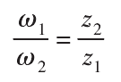
Where, ω 1 and ω 2 are the rotation speed and revolution speed of the rolling wheel respectively, rad / S; Z1 and Z2 are the number of teeth of the rolling wheel and the target gear respectively.
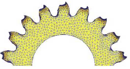
The purpose of dividing teeth is to ensure that after the rolling wheel bites into the surface of the blank, the rolling wheel can rotate one circle on the outer circle surface of the blank to evenly divide the teeth on the outer circle surface of the blank. However, in the rolling process, due to the friction between the rolling wheel and the blank, the rotation speed mismatch and other factors cause unreasonable tooth division, which will cause folding phenomenon in the continuous rolling process, as shown in Fig. 1.
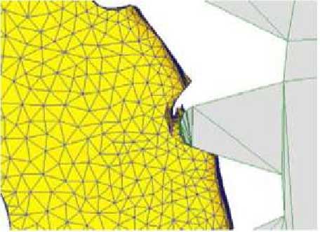
The rolling process of gear is a non occlusive local extrusion deformation process, and the material deformation is complex, including non deformation area, to be deformed area, deformation area and final deformation area. In the rolling process, due to the asymmetric deformation on both sides of the tooth profile, the lug phenomenon occurs at the tooth top, as shown in Fig. 2.
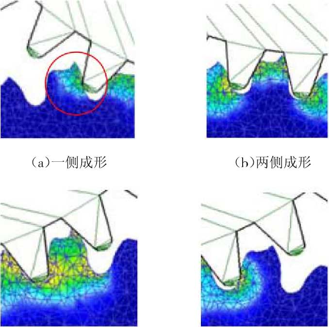
The cause of asymmetric deformation of the tooth profile is analyzed from the formation process of a tooth profile, as shown in Fig. 3. It can be seen from Figure 3 (a) that the roller contacts one side of the billet gear, and the material is partially deformed. Subsequently, both sides of the tooth profile are subjected to the action of rolling wheels (see Fig. 3 (b)). With the rolling process going on, only the other side of the tooth profile is deformed (see Fig. 3 (c)). Finally, the rolling wheel leaves the blank (see Fig. 3 (d)) to complete the forming process of the tooth profile. With the increase of feed rate, the tooth profile of the target tooth becomes higher and higher until the whole profile is formed.