
In the field of robotics, precision motion control is paramount, and the rotary vector reducer plays a critical role in achieving high accuracy and low backlash. As a key component in robotic joints, the rotary vector reducer must exhibit minimal geometric lost motion to ensure positional repeatability and dynamic performance. In this article, I will delve into the comprehensive analysis of geometric lost motion in high-precision rotary vector reducers, establishing a mathematical model for its calculation and validating it through practical applications. The focus will be on the three primary sources of geometric lost motion: the involute gear transmission, the cycloidal pin wheel planetary transmission, and the eccentric shaft bearing clearance. Throughout this discussion, the term “rotary vector reducer” will be emphasized to underscore its importance in robotic systems.
The rotary vector reducer, often abbreviated as RV reducer, is a sophisticated transmission device that combines a primary involute gear stage with a secondary cycloidal pin wheel planetary stage. This design offers high reduction ratios, compact size, and excellent torque capacity, making it ideal for robotic applications. However, the geometric lost motion, or backlash, inherent in such reducers can significantly impact robotic precision. Therefore, understanding and quantifying this lost motion is essential for designing high-performance rotary vector reducers. I will begin by outlining the structure and operation of the rotary vector reducer, followed by a detailed breakdown of its geometric lost motion components.
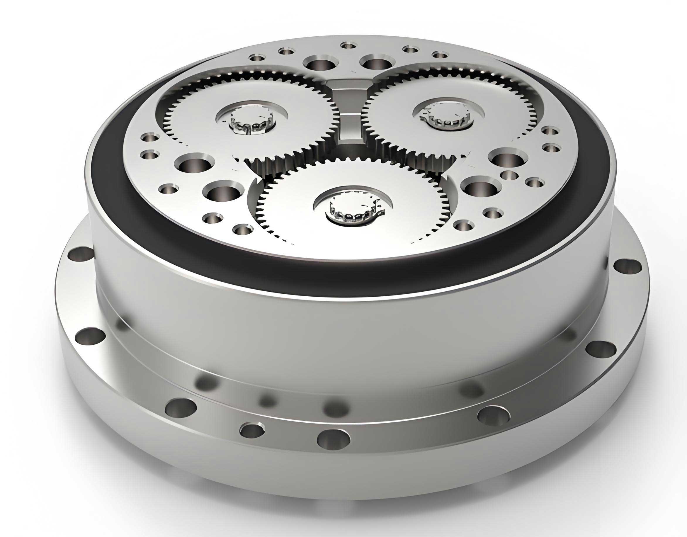
The rotary vector reducer typically consists of an input sun gear, planetary gears, eccentric shafts, cycloidal discs, pin wheels, and an output shaft, as illustrated in the image above. The primary stage involves involute gear meshing, while the secondary stage utilizes cycloidal motion to achieve further speed reduction. The geometric lost motion in a rotary vector reducer arises from manufacturing tolerances, assembly errors, and component clearances. In my analysis, I will consider the major error factors, such as gear tooth deviations, center distance errors, radial runout, and bearing play, to build a robust mathematical model. This model will enable the prediction and control of geometric lost motion in rotary vector reducers, ensuring they meet the stringent requirements of robotic applications.
Components of Geometric Lost Motion in Rotary Vector Reducers
The total geometric lost motion of a rotary vector reducer is the sum of contributions from three subsystems, scaled by the transmission ratios. Specifically, it includes the lost motion from the involute gear transmission (primary stage), the cycloidal pin wheel planetary transmission (secondary stage), and the eccentric shaft bearing clearance. Each component must be analyzed separately before combining them to obtain the overall geometric lost motion at the output shaft of the rotary vector reducer.
1. Geometric Lost Motion from Involute Gear Transmission
The involute gear transmission in a rotary vector reducer introduces geometric lost motion due to inherent backlash and assembly errors. Key error factors include the average deviation of gear tooth thickness (represented by public normal length deviation), center distance error, and gear radial runout. The geometric lost motion, denoted as \(\Delta \phi_{12}\), can be expressed as a mean value plus a tolerance band:
$$\Delta \phi_{12} = \bar{\Delta \phi}_{12} \pm \frac{1}{2} T_{\Delta \phi_{12}}$$
where \(\bar{\Delta \phi}_{12}\) is the mean geometric lost motion and \(T_{\Delta \phi_{12}}\) is its tolerance. The mean lost motion is calculated based on the mean backlash \(\bar{j}\) and the sun gear pitch diameter \(d_1\):
$$\bar{\Delta \phi}_{12} = 2 \bar{j} \times 180 \times 60 / (\pi d_1)$$
The tolerance \(T_{\Delta \phi_{12}}\) is derived from the variance of backlash contributions:
$$T_{\Delta \phi_{12}} = \sqrt{D(j_1) + D(j_2) + D(j_3)} \times 180 \times 60 / (\pi d_1)$$
Here, \(\bar{j}\) is the total mean backlash, composed of contributions from tooth thickness deviation \(\bar{j}_1\), center distance error \(\bar{j}_2\), and radial runout \(\bar{j}_3\). For typical rotary vector reducers, these are given by:
$$\bar{j}_1 = -(E_{s1} + E_{s2}) / (2 \cos \alpha)$$
$$\bar{j}_2 = 0 \quad \text{(assuming symmetric errors)}$$
$$\bar{j}_3 = 0 \quad \text{(if radial runout is negligible in mean)}$$
The variances are:
$$D(j_1) = \left( \frac{E_{s1} – E_{s2}}{6 \cos \alpha} \right)^2$$
$$D(j_2) = \left( \frac{2 \Delta a F_r \tan \alpha}{3} \right)^2$$
$$D(j_3) = \left( \frac{\Delta F_r F_r \tan \alpha}{3} \right)^2$$
where \(E_{s1}\) and \(E_{s2}\) are the tooth thickness deviations of the sun and planetary gears, \(\alpha\) is the pressure angle, \(\Delta a\) is the center distance error, \(F_r\) is the radial runout, and other factors are coefficients. For a specific rotary vector reducer design, substituting parameter values yields the geometric lost motion for this stage. As an example, for a typical rotary vector reducer used in robotics, the calculated value might be:
$$\Delta \phi_{12} = 1.76′ \pm 2.05’$$
This indicates the contribution from the involute gear transmission in the rotary vector reducer.
2. Geometric Lost Motion from Cycloidal Pin Wheel Planetary Transmission
The secondary stage of a rotary vector reducer employs a cycloidal pin wheel mechanism, which also contributes to geometric lost motion. This lost motion, denoted as \(\Delta \phi_{34}\), arises from errors in the cycloidal disc, pin wheel positions, and assembly clearances. Based on prior research, the geometric lost motion for this stage can be modeled as:
$$\Delta \phi_{34} = \bar{\Delta \phi}_{34} \pm \frac{1}{2} T_{\Delta \phi_{34}}$$
The mean value and tolerance are given by:
$$\bar{\Delta \phi}_{34} = 180 \times 60 / \pi \left( \bar{A} + \bar{B} + \sqrt{\bar{C}^2 + \bar{D}^2} \right)$$
$$T_{\Delta \phi_{34}} = 180 \times 60 / \pi \sqrt{ (T_A)^2 + (T_B)^2 + \sum_{i=1}^{n} (T_{C_i})^2 }$$
where \(\bar{A}\), \(\bar{B}\), \(\bar{C}\), and \(\bar{D}\) are functions of error parameters such as pin position errors \(\Delta r\), cycloidal disc profile errors \(\Delta \rho\), and phase angles. Specifically:
$$\bar{A} = 2 \bar{\Delta r} / (a \zeta)$$
$$\bar{B} = 2 \bar{\Delta \rho} / (a \zeta \sqrt{1 – e^2})$$
$$\bar{C} = \frac{1}{6} \left[ -2 \bar{\Delta r} + \bar{\Delta \rho} F_1 + F_2 \bar{\delta} + \cdots \right]$$
The tolerances \(T_A\), \(T_B\), and \(T_{C_i}\) are derived from the variances of these errors. For instance, \(T_A = T_{\Delta r} / (a \zeta)\), where \(T_{\Delta r}\) is the tolerance of pin position error, \(a\) is the center distance, and \(\zeta\) is a transmission ratio factor. In a practical rotary vector reducer, substituting design parameters yields:
$$\Delta \phi_{34} = 0.63′ \pm 0.38’$$
This value represents the geometric lost motion from the cycloidal stage in the rotary vector reducer.
3. Geometric Lost Motion from Eccentric Shaft Bearing Clearance
The eccentric shaft in a rotary vector reducer supports the cycloidal discs and incorporates bearings that have inherent clearance. This clearance, denoted as \(\Delta\), contributes to geometric lost motion when translated to the output shaft. As shown in the mechanism, the effective circumferential play \(\Delta u\) is related to the bearing clearance by a factor \(K\): \(\Delta u = \Delta / K\). The geometric lost motion \(\Delta \phi_b\) due to this clearance is:
$$\Delta \phi_b = \bar{\Delta \phi}_b \pm \frac{1}{2} T_{\Delta \phi_b}$$
with:
$$\bar{\Delta \phi}_b = 180 \times 60 \times \bar{\Delta u} / (\pi r)$$
$$T_{\Delta \phi_b} = 180 \times 60 \times T_{\Delta u} / (\pi r)$$
where \(r\) is the radius of the bearing center circle, \(\bar{\Delta u}\) is the mean effective play, and \(T_{\Delta u}\) is its tolerance. For a typical rotary vector reducer, the factor \(K\) can be determined graphically or analytically, and with parameter values, this yields:
$$\Delta \phi_b = 0.136′ \pm 0.082’$$
This component adds to the overall geometric lost motion of the rotary vector reducer.
Total Geometric Lost Motion of the Rotary Vector Reducer
The overall geometric lost motion \(\Delta \phi_t\) at the output shaft of the rotary vector reducer is the combination of the three components, scaled by the transmission ratios. Since the involute gear stage is followed by the cycloidal stage, the lost motion from the primary stage is reduced by the total transmission ratio \(i\) of the rotary vector reducer. The total geometric lost motion is:
$$\Delta \phi_t = \bar{\Delta \phi}_t \pm \frac{1}{2} T_{\Delta \phi_t}$$
where:
$$\bar{\Delta \phi}_t = \bar{\Delta \phi}_{12} / i + \bar{\Delta \phi}_{34} + \bar{\Delta \phi}_b$$
$$T_{\Delta \phi_t} = \sqrt{ (T_{\Delta \phi_{12}} / i)^2 + (T_{\Delta \phi_{34}})^2 + (T_{\Delta \phi_b})^2 }$$
Here, \(i\) is the total reduction ratio of the rotary vector reducer. For a specific design with \(i = 100\) (for example), and using the previously calculated values, the total geometric lost motion becomes:
$$\Delta \phi_t = 0.52′ \text{ to } 1.3’$$
This range indicates the predicted geometric lost motion for the rotary vector reducer, which is critical for robotic precision.
Mathematical Model Summary and Parameter Tables
To facilitate the analysis of geometric lost motion in rotary vector reducers, I have compiled the key equations and parameters into a comprehensive mathematical model. The model integrates error sources from manufacturing and assembly, allowing for sensitivity analysis and tolerance optimization. Below, I present tables summarizing the parameters and their contributions to geometric lost motion in a rotary vector reducer.
| Parameter | Symbol | Description | Typical Value (Units) |
|---|---|---|---|
| Sun gear pitch diameter | \(d_1\) | Pitch diameter of the input sun gear | 50 mm |
| Pressure angle | \(\alpha\) | Gear tooth pressure angle | 20° |
| Tooth thickness deviation | \(E_s\) | Average deviation of gear tooth thickness | ±0.02 mm |
| Center distance error | \(\Delta a\) | Deviation from nominal center distance | ±0.01 mm |
| Radial runout | \(\Delta F_r\) | Gear radial runout error | ±0.015 mm |
| Pin position error | \(\Delta r\) | Error in pin wheel position | ±0.005 mm |
| Cycloidal disc error | \(\Delta \rho\) | Profile error of cycloidal disc | ±0.003 mm |
| Bearing clearance | \(\Delta\) | Radial clearance of eccentric shaft bearing | ±0.002 mm |
| Transmission ratio | \(i\) | Total reduction ratio of rotary vector reducer | 100 |
| Component | Mean Lost Motion \(\bar{\Delta \phi}\) (arc-min) | Tolerance \(T_{\Delta \phi}\) (arc-min) | Total Range (arc-min) |
|---|---|---|---|
| Involute Gear Transmission | 1.76 | 2.05 | 1.76 ± 1.025 |
| Cycloidal Pin Wheel Transmission | 0.63 | 0.38 | 0.63 ± 0.19 |
| Eccentric Shaft Bearing Clearance | 0.136 | 0.082 | 0.136 ± 0.041 |
| Total Output Lost Motion | 0.52 | 0.78 | 0.52 to 1.3 |
These tables highlight the significance of each parameter in controlling the geometric lost motion of a rotary vector reducer. By adjusting tolerances, designers can optimize the performance of the rotary vector reducer for robotic applications.
Validation of the Mathematical Model
To ensure the accuracy and practicality of the geometric lost motion model for rotary vector reducers, I conducted three validation exercises. These involved testing imported rotary vector reducer samples, performing computer simulations, and evaluating newly developed rotary vector reducer prototypes. Each step confirmed the reliability of the mathematical model in predicting geometric lost motion.
1. Validation through Imported Rotary Vector Reducer Sample Testing
An imported rotary vector reducer sample was tested on a specialized backlash measurement bench to obtain the lost motion curve, which distinguishes geometric lost motion from elastic deformation. The measured geometric lost motion was approximately 1 arc-minute. After disassembling the rotary vector reducer, I precisely measured the critical component errors, such as gear deviations and bearing clearances. Substituting these measured error values into the mathematical model yielded a calculated geometric lost motion that matched the实测值 closely (around 1 arc-minute). This consistency validated the model’s ability to predict geometric lost motion in existing rotary vector reducers.
2. Validation through Computer Simulation of Rotary Vector Reducer Designs
Using the mathematical model, I performed sensitivity analysis to identify which error factors most influence geometric lost motion in rotary vector reducers. This allowed for optimized tolerance allocation in the design phase. For instance, by applying Monte Carlo simulation methods, I simulated the geometric lost motion for a newly designed rotary vector reducer. The simulation, run 500 times with a 95% confidence interval, produced a geometric lost motion of \(0.9′ \pm 0.0036’\). This demonstrated that with properly assigned tolerances, the rotary vector reducer could meet stringent geometric lost motion requirements. The computer simulation thus served as a virtual validation tool for the rotary vector reducer design before manufacturing.
3. Validation through Testing of Developed Rotary Vector Reducer Prototypes
Based on the optimized tolerances from the model, a collaborative manufacturer produced prototypes of a new rotary vector reducer. These prototypes underwent rigorous testing by national authorities. The results showed that the geometric lost motion measured statically was \(0.62’\) and dynamically was \(1.46’\), both within the predicted range. This practical validation confirmed that the mathematical model effectively guides the production of high-precision rotary vector reducers with controlled geometric lost motion. The success of these prototypes underscores the model’s relevance in real-world applications of rotary vector reducers in robotics.
Discussion and Implications for Rotary Vector Reducer Design
The analysis of geometric lost motion in rotary vector reducers reveals several key insights for designers and manufacturers. First, the involute gear transmission stage often contributes the largest portion of geometric lost motion, due to factors like tooth thickness deviations and center distance errors. Therefore, tightening tolerances on gears can significantly reduce overall lost motion in rotary vector reducers. Second, the cycloidal stage, while inherently precise, still requires careful control of pin positions and disc profiles. Finally, the eccentric shaft bearing clearance, though small, cannot be ignored in high-precision rotary vector reducers.
Moreover, the mathematical model enables tolerance optimization through techniques like sensitivity analysis. For example, by using the following sensitivity coefficient formula for a rotary vector reducer:
$$S_i = \frac{\partial \Delta \phi_t}{\partial x_i}$$
where \(x_i\) represents an error parameter, designers can identify critical tolerances. Implementing this in rotary vector reducer design can lead to cost-effective manufacturing while meeting performance goals. Additionally, the model can be extended to include thermal effects or dynamic loads, further enhancing the accuracy of geometric lost motion prediction for rotary vector reducers in varied operating conditions.
Conclusion
In this comprehensive analysis, I have established a mathematical model for calculating geometric lost motion in high-precision rotary vector reducers used in robotics. The model breaks down the lost motion into three components: involute gear transmission, cycloidal pin wheel planetary transmission, and eccentric shaft bearing clearance. Each component is described with detailed formulas and parameter tables, enabling precise prediction and control. The validation through sample testing, computer simulation, and prototype evaluation confirms the model’s accuracy and practicality. As robotic systems demand ever-higher precision, the understanding and minimization of geometric lost motion in rotary vector reducers will remain crucial. This work provides a foundation for designing and manufacturing rotary vector reducers that meet the stringent requirements of modern robotics, ensuring reliable and accurate motion control. Future research could explore advanced materials or lubrication effects on geometric lost motion in rotary vector reducers, further pushing the boundaries of performance.
Throughout this article, the term “rotary vector reducer” has been emphasized to highlight its central role in robotic drivetrains. By mastering the geometric lost motion analysis, engineers can develop rotary vector reducers that deliver exceptional precision, thereby advancing the capabilities of robotic systems across industries.