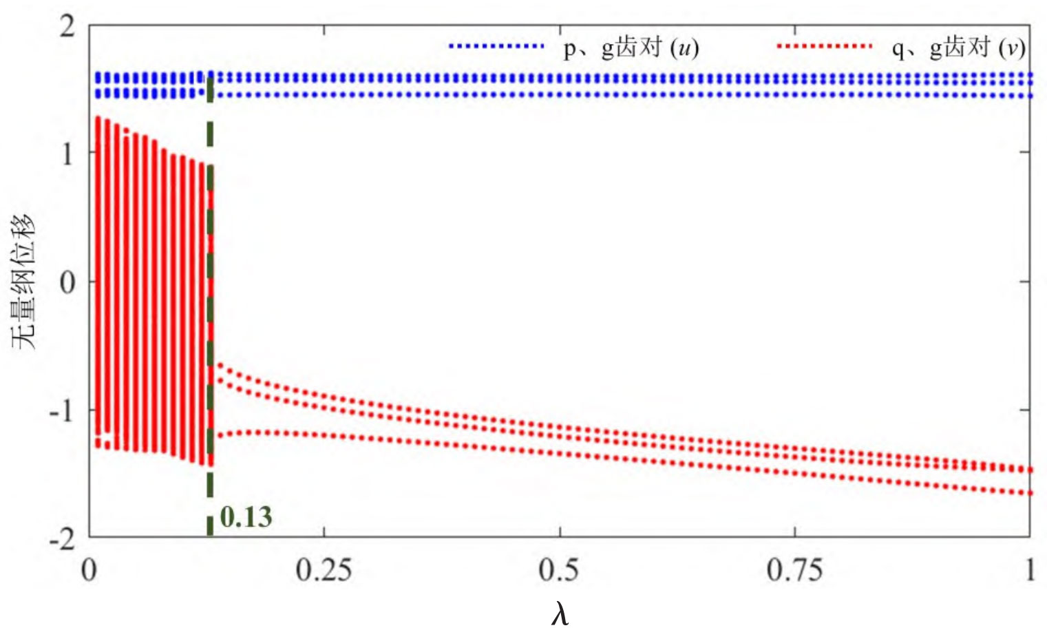
Figure 1 shows the dimensionless vibration displacement u and v of p, g tooth pairs, and q, g tooth pairs as a function of load ratio λ A bifurcation diagram of changes. For p and g tooth pairs, as the load ratio of the helical gear increases, the system sequentially undergoes quasi periodic motion( λ= 0 → 0.13) and stable three period motion state( λ= 0.13→1)。 For the q and g tooth pairs, as the load ratio of the helical gear increases, the system exhibits chaotic motion and three periodic motion states. Compared to the light load condition, the nonlinear range (chaotic state and quasi periodic motion state) of the system during heavy load is narrower, indicating that when adjusting the parallel input helical gear load ratio of the system, the heavy load system is more likely to avoid the unstable range and enter a stable periodic motion state.
Figures 2-3 show the system under different load ratios on helical gears λ The dynamic characteristics of the dimensionless vibration displacement u at time. When λ When it is 0.1, the parameter u oscillates within the range (1.4, 1.6), indicating that the p and g tooth pairs are always in a positive tooth meshing state. The FFT diagram contains obvious peak frequencies of 0.5 (fundamental frequency), 1.0 (second harmonic), and 1.5 (third harmonic). The system phase diagram presents a closed curve with multiple winding cycles, and the points on the Poincar é section are mainly concentrated near three points. At this time, the system approximately corresponds to three periodic motion. When λ When it is 0.8, the parameter u exhibits periodic vibration within the interval (1.4, 1.6), and its phase diagram and Poincar é cross-section indicate that the system exhibits a stable three period motion state.
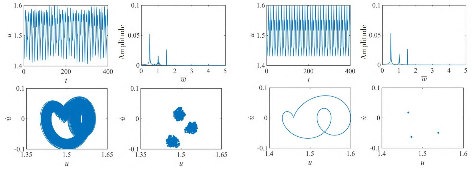
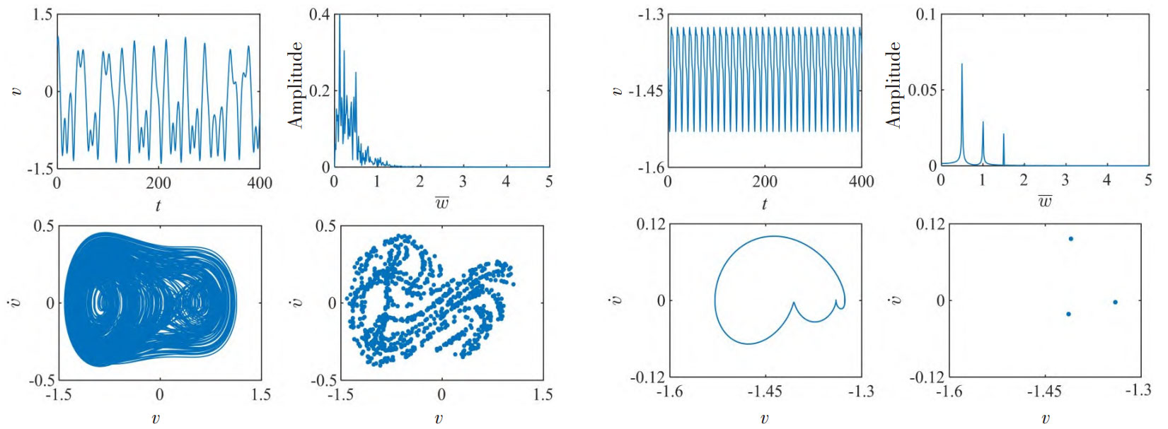
Figure 4-5 shows the system under different load ratios on helical gears λ The dynamic characteristics of the dimensionless vibration displacement v at time. When λ When it is 0.1, the dynamic behavior of parameter v is similar to that of light load conditions, specifically manifested as oscillation within the range (-1.5, 1.5), where the q and g tooth pairs have three motion states during the motion process: forward tooth meshing, disengagement, and back tooth meshing, with alternating front and back impacts of the gear teeth. The FFT plot presents a discrete spectrum with a certain width. At the same time, its phase space trajectories and Poincar é cross sections indicate that the system is in a chaotic state. When λ When it is 0.8, the parameter v oscillates periodically within the range (-1.6, -1.3), indicating that the q and g tooth pairs are always in a back tooth meshing state. The frequency domain signal of meshing displacement exhibits peak frequencies of 0.5 (fundamental frequency), 1.0 (second harmonic), and 1.5 (third harmonic) simultaneously, and the amplitude gradually decreases. The phase diagram and Poincar é cross-section indicate that the system exhibits a stable three period motion state.