
Traditional approaches to helical gear forging often relied on classical mechanics, proving inadequate for complex geometries like spiral bevel gears. These methods struggled with irregular shapes, lacked robust data support, and made process optimization costly and time-consuming. To overcome these limitations, we redesigned the forging process using closed-die warm forging and leveraged DEFORM software for comprehensive finite element analysis (FEA). This study meticulously examines material flow, stress-strain behavior, and thermal effects to identify defect root causes and optimize the gear forging process for superior outcomes.
1. Closed-Die Warm Forging Process Design
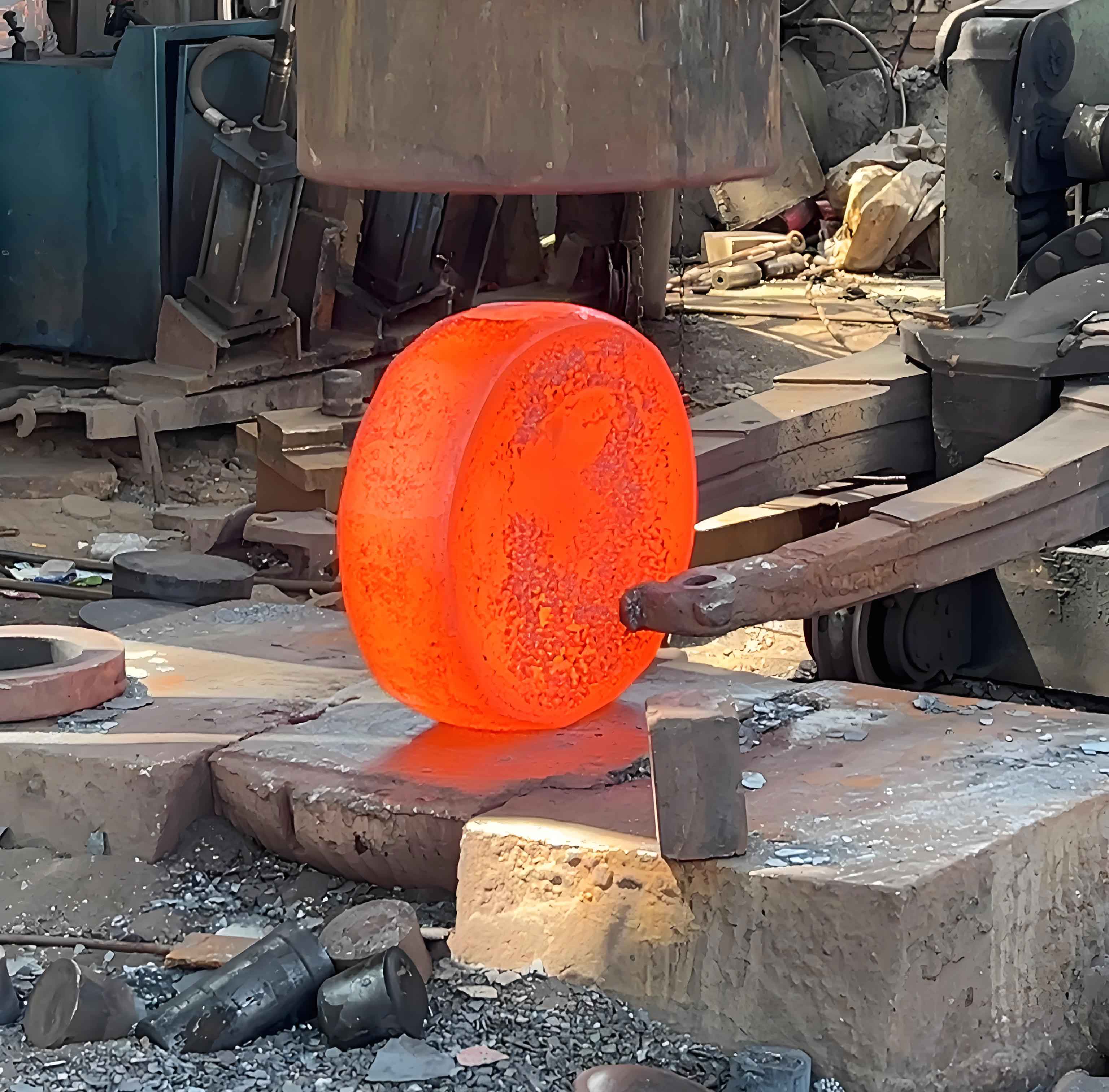
Our optimized helical gear forging consolidates production into two stages: blanking and finish forging. This single-impression closed-die design simplifies the process while enhancing precision. Crucially, we transitioned from cold to warm forging (1000°C initial billet temperature), significantly reducing deformation resistance and improving die filling. The closed-die approach minimizes flash formation, boosts material utilization, and yields gears with excellent surface integrity, fatigue resistance, and dimensional accuracy compared to machining or open-die gear forging. Thermal interactions between the billet and dies (preheated to 65°C) are explicitly modeled, acknowledging their impact on flow stress and final metallurgical properties. The initial cylindrical billet (Ø35 mm × 20 mm) is sized close to the gear root diameter to facilitate efficient cavity filling during gear forging.
2. Finite Element Model Setup for Gear Forging
A high-fidelity 3D model of the helical gear and dies was constructed within DEFORM-3D™. The billet material, AISI-1045 carbon steel, and the die material, H13 tool steel, were assigned appropriate constitutive models accounting for temperature-dependent plasticity and heat transfer. A fine mesh of approximately 150,000 tetrahedral elements ensured accuracy in capturing intricate tooth geometry and localized deformation during gear forging. Key boundary conditions included:
- Coulomb friction coefficient (μ = 0.25) at billet-die interfaces
- Upper die velocity: 15 mm/s
- Lower die velocity: 7.5 mm/s
- Heat transfer coefficient: 11 N/(sec mm °C)
The flow stress behavior of AISI-1045 steel is governed by a modified Hensel-Spittel equation, critical for accurate warm forging simulation:
$$ \sigma_f = A \cdot e^{m_1 T} \cdot \varepsilon^{m_2} \cdot \dot{\varepsilon}^{m_3} \cdot e^{m_4 / \varepsilon} \cdot (1 + \varepsilon)^{m_5 T} \cdot e^{m_7 \varepsilon} \cdot \dot{\varepsilon}^{m_8 T} \cdot T^{m_9} $$
Where \( \sigma_f \) is the flow stress, \( \varepsilon \) is the strain, \( \dot{\varepsilon} \) is the strain rate, \( T \) is temperature, and \( A, m_1, …, m_9 \) are material-specific constants determined experimentally. Table 1 details the complete process parameters.
| Parameter | Value | Parameter | Value |
|---|---|---|---|
| Billet Material | AISI-1045 | Upper Die Velocity | 15 mm/s |
| Die Material | H13 | Lower Die Velocity | 7.5 mm/s |
| Billet Temp. | 1000 °C | Mesh Elements | 150,000 |
| Die Temp. | 65 °C | Friction Coefficient (μ) | 0.25 |
3. Simulation Results: Deformation Mechanics in Gear Forging
3.1 Velocity Field Analysis
The velocity field reveals metal flow patterns critical for defect-free gear forging. At 50% reduction (Figure 2a), initial tooth formation occurs near the root circle. Metal velocity is highest at the billet top (15.2 mm/s) due to direct upper die contact, while minimal flow (8 mm/s) exists at the root where deformation initiates. By 75% reduction (Figure 2b), tooth contours are established. Velocity peaks at the root circle (18 mm/s) as material accelerates into tooth cavities, while the tooth tip exhibits lower velocity (8 mm/s) due to constrained flow. At final reduction (100%, Figure 2c), flow ceases as the cavity fills completely. The velocity gradient \( \nabla \vec{v} \) directly influences strain rate distribution \( \dot{\varepsilon} \):
$$ \dot{\varepsilon}_{ij} = \frac{1}{2} \left( \frac{\partial v_i}{\partial x_j} + \frac{\partial v_j}{\partial x_i} \right) $$
3.2 Stress-Strain Distribution
Effective strain \( \bar{\varepsilon} \) quantifies cumulative plastic deformation. At 50% reduction (Figure 3a), strain concentrates at the root circle (ε ≈ 0.6) as material begins filling cavities, while the billet core remains low (ε ≈ 0.035). By 75% reduction (Figure 3b), strain intensifies near the root (ε ≈ 0.8) and distributes more uniformly (ε ≈ 0.5) across formed teeth. A distinctive low-strain zone (ε ≈ 0.08) persists under the upper die contact. At completion (Figure 3c), maximum strain localizes at the root circle, and the top surface develops a low-strain region with minor flash (ε ≈ 0.323). The effective stress \( \bar{\sigma} \) follows von Mises criterion:
$$ \bar{\sigma} = \sqrt{\frac{3}{2} \sigma’_{ij} \sigma’_{ij}} \quad \text{where} \quad \sigma’_{ij} = \sigma_{ij} – \frac{1}{3}\sigma_{kk}\delta_{ij} $$
Stress peaks correlate with areas of severe constraint and friction, notably at the root circle.
3.3 Temperature Effects on Gear Forging
Forging temperature profoundly impacts flow stress and formability. Simulations compared cold (20°C), warm (600°C), and hot forging (1000°C). Figure 4 shows strain distributions. Cold forging exhibited incomplete cavity filling (root strain ε ≈ 1.2, outer strain ε ≈ 0.285) due to high flow stress. Warm forging (600°C) improved filling (root ε ≈ 0.9, outer ε ≈ 0.268), while hot forging (1000°C) achieved complete filling with slightly higher strain (root ε ≈ 1.1, outer ε ≈ 0.275). Crucially, flow stress \( \sigma_f \) decreased exponentially with temperature (Figure 5):
| Temperature (°C) | Root Strain (ε) | Outer Strain (ε) | Root Stress (MPa) | Outer Stress (MPa) |
|---|---|---|---|---|
| 20 | 1.20 | 0.285 | 1000 | 890 |
| 600 | 0.90 | 0.268 | 730 | 550 |
| 1000 | 1.10 | 0.275 | 600 | 300 |
The relationship between temperature \( T \), strain rate \( \dot{\varepsilon} \), and flow stress is captured by the Zener-Hollomon parameter \( Z \):
$$ Z = \dot{\varepsilon} \exp\left(\frac{Q}{RT}\right) $$
$$ \sigma_f = C \cdot \ln\left( \left( \frac{Z}{A} \right)^{1/n} + \sqrt{ \left( \frac{Z}{A} \right)^{2/n} + 1 } \right) $$
Where \( Q \) is activation energy, \( R \) is gas constant, and \( C, A, n \) are material constants. This explains the significant stress reduction at 1000°C (root σ ≈ 600 MPa) vs. cold forging (root σ ≈ 1000 MPa).
4. Defect Analysis and Process Optimization in Gear Forging
Simulation identified critical defects inherent to helical gear forging. Underfilling (Figure 6a) occurred primarily at the helical tooth root circle due to high frictional resistance impeding metal flow into sharp corners. Flash formation (Figure 6b) resulted from excessive radial material flow escaping the die cavity, exacerbated by suboptimal billet volume or insufficient die clamping. The persistent low-strain zone under the upper die indicated minimal work hardening in that region. Optimization strategies were derived:
- Temperature Control: Maintain billet temperature at 1000°C ± 20°C to ensure low flow stress and adequate ductility for complete cavity filling in gear forging.
- Billet Volume Optimization: Adjust initial billet diameter to Ø35.2 mm for precise cavity filling without excess flash.
- Friction Reduction: Apply advanced graphite-based lubricants to reduce μ below 0.2, enhancing root filling.
- Die Design Refinement: Incorporate slight corner radii (R0.5 mm) at tooth root transitions to reduce stress concentration and improve metal flow.
- Strain Homogenization: Implement a two-stage forging approach: initial preform design to distribute strain more evenly before finish forging.
The optimized process achieved near-net shape helical gears (Figure 6c) with complete tooth filling, minimal flash, uniform microstructure, and enhanced mechanical properties essential for demanding gear forging applications.
5. Conclusion
This study successfully demonstrates the redesign and optimization of helical gear forging using closed-die warm forging and DEFORM-based FEA. Key findings reveal that metal flow velocity peaks during intermediate reduction stages (75%), particularly at the root circle where deformation is most intense. Stress and strain concentrate significantly at the root due to geometric constraints and friction, with maximum values reaching 600 MPa and 1.1 effective strain, respectively, at 1000°C. Temperature is the dominant factor influencing formability; increasing from 20°C to 1000°C reduced flow stress by approximately 40% and enabled complete die filling. Process optimizations focused on temperature stability, billet sizing, friction management, and die geometry refinement effectively eliminated underfilling and minimized flash. This validated approach produces helical gears with superior dimensional accuracy, surface quality, fatigue resistance, and material efficiency compared to conventional methods, establishing a robust framework for complex gear forging process design.