
In my experience with rolling mill systems, the herringbone gear stand plays a critical role in transmitting torque and ensuring smooth operation. Over the years, I have observed that herringbone gear stands, particularly in heavy-duty applications, often face premature failure due to structural issues, especially with sliding bearings. This article delves into a detailed analysis of transforming a 1,100 mm herringbone gear stand by replacing sliding bearings with rolling bearings, based on practical challenges and solutions. The focus is on enhancing reliability, reducing maintenance, and improving performance, with an emphasis on the herringbone gear mechanism throughout.
The herringbone gear stand is integral to rolling mill drives, operating under low-speed, high-torque conditions with frequent impact loads. Traditionally, herringbone gear stands employ sliding bearings for their radial compactness and load-bearing capacity. However, in practice, these sliding bearings in herringbone gear configurations often suffer from early failures due to factors like poor lubrication, misalignment, and excessive wear. This leads to downtime and increased costs. In this analysis, I explore the root causes and propose a transformation using rolling bearings, which offer better precision and durability for herringbone gear systems.
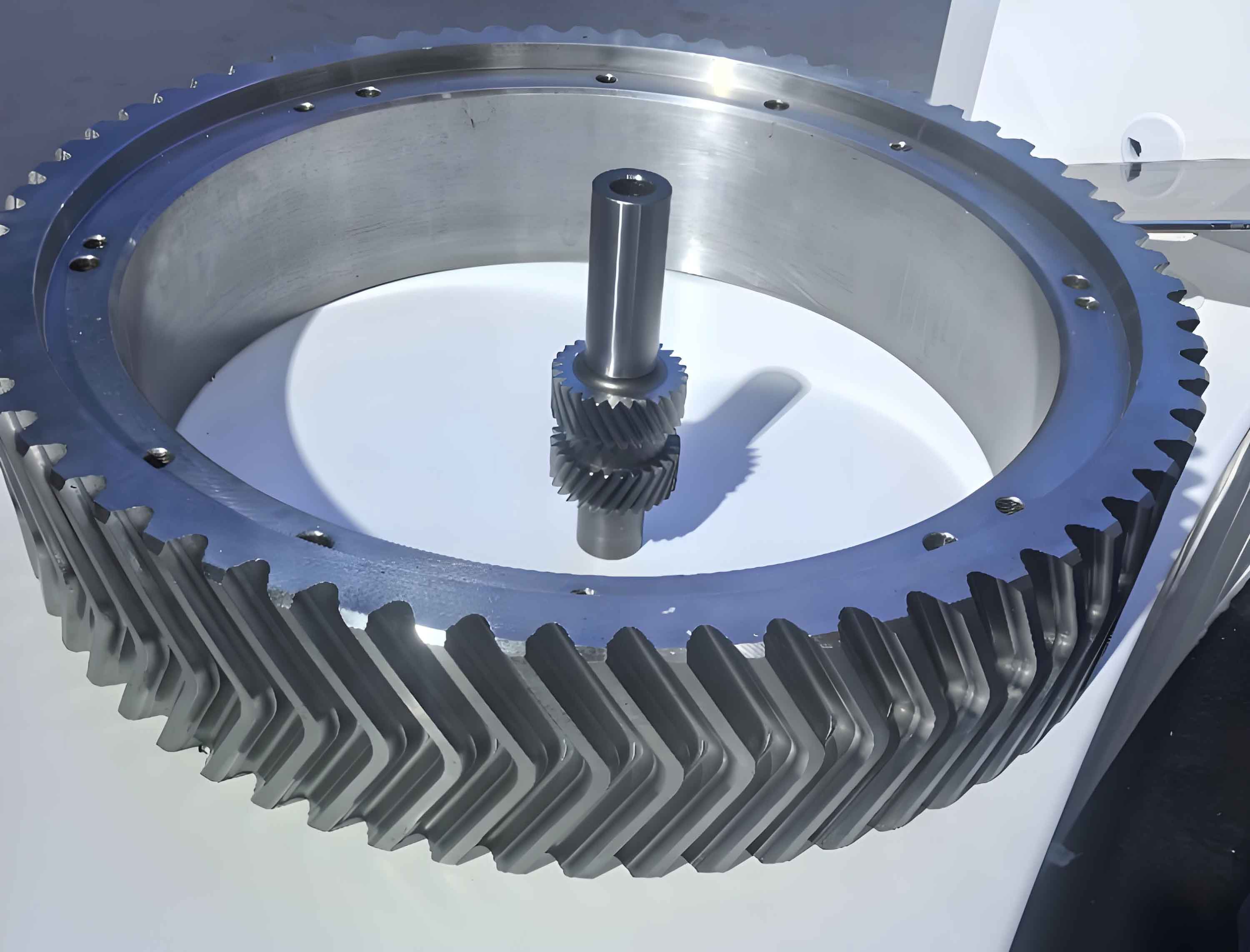
To understand the issues, let’s first examine the original herringbone gear stand structure. The herringbone gear stand consists of two shafts—an input shaft and an output shaft—connected via herringbone gears that provide smooth torque transmission without axial thrust. In the 1,100 mm herringbone gear stand, the shafts were supported by sliding bearings, and the gear teeth were designed for a center distance of 1,100 mm. The operating conditions included a maximum torque of 2.16 × 10^3 kN·m, speeds ranging from 70 to 110 rpm, and reversible operation. The herringbone gear teeth mesh in a way that cancels axial forces, but radial loads remain significant, often exceeding 2,000 kN. This radial load is a key factor in bearing performance.
The primary problems with the original herringbone gear stand stemmed from the sliding bearings. Sliding bearings require high installation precision; any misalignment can disrupt oil film formation, leading to increased friction, overheating, and accelerated wear. For herringbone gears, misalignment also causes uneven tooth contact, reducing the herringbone gear’s lifespan and increasing vibration. Additionally, sliding bearings have inherent clearance issues: too small a clearance causes thermal expansion problems, while too large a clearance reduces load capacity and induces冲击. In herringbone gear stands, this often resulted in excessive gear backlash, with center distance deviations over 1 mm, compromising the herringbone gear mesh and leading to dynamic overloads.
To quantify these issues, I analyzed the forces in the herringbone gear system. The radial force \( F_r \) on the bearings can be derived from the torque transmission. For a herringbone gear pair, the tangential force \( F_t \) is given by:
$$ F_t = \frac{2T}{d} $$
where \( T \) is the torque and \( d \) is the pitch diameter. The radial force \( F_r \) for herringbone gears is:
$$ F_r = F_t \cdot \tan(\alpha) $$
with \( \alpha \) being the pressure angle (typically 20°). Given the maximum torque of 2.16 × 10^3 kN·m and a pitch diameter of approximately 1,100 mm for the herringbone gear, the radial force calculates to around 2,140 kN. This high radial load exacerbates sliding bearing wear. Moreover, the axial force \( F_a \) in herringbone gears is theoretically zero due to the opposing helices, but in practice, minor imbalances can occur, adding to bearing stress.
The failure modes of sliding bearings in herringbone gear stands include wear, scoring, and deformation. Table 1 summarizes common issues and their impacts on herringbone gear performance.
| Issue | Impact on Herringbone Gear Stand | Typical Frequency |
|---|---|---|
| Bearing Misalignment | Uneven tooth contact, reduced herringbone gear life | High |
| Excessive Clearance | Increased backlash, herringbone gear vibration | Moderate |
| Lubrication Failure | Overheating, herringbone gear seizure | Low |
| Load Fluctuations | Fatigue in herringbone gear teeth | High |
To address these, I considered various improvements, such as enhancing lubrication or using advanced materials, but the structural limitations of sliding bearings in herringbone gear stands persisted. Thus, I proposed a transformation to rolling bearings, which offer higher precision, lower friction, and better load distribution for herringbone gear applications. Rolling bearings, particularly multi-row cylindrical roller bearings, can handle high radial loads while accommodating minor axial shifts, making them ideal for herringbone gear stands.
In the transformation plan, the key step was selecting an appropriate rolling bearing for the herringbone gear stand. The bearing must fit within the existing space and withstand the radial loads. For the 1,100 mm herringbone gear stand, I chose a four-row cylindrical roller bearing due to its high radial capacity and stability. The selection criteria involved calculating the bearing life and dimensions. The basic dynamic load rating \( C \) and radial load \( P_r \) are used in the life formula:
$$ L_{10} = \left( \frac{C}{P_r} \right)^p $$
where \( p = 10/3 \) for roller bearings. For the herringbone gear stand, \( P_r = F_r = 2,140 \text{ kN} \). With a candidate bearing having \( C = 36,613 \text{ kN} \), the calculated life is:
$$ L_{10} = \left( \frac{36,613}{2,140} \right)^{10/3} \approx 43,758 \text{ hours} $$
This exceeds the typical service requirements for herringbone gear stands. The bearing dimensions were constrained by the center distance \( A = 1,100 \text{ mm} \). According to design guidelines, the bearing inner diameter \( d \) should be:
$$ d = (0.5 \text{ to } 0.6) \times A $$
yielding \( d \approx 550 \text{ to } 660 \text{ mm} \). The outer diameter \( D \) must satisfy:
$$ D \leq A – (40 \text{ to } 70 \text{ mm}) $$
so \( D \leq 1,060 \text{ to } 1,030 \text{ mm} \). I selected a bearing with \( d = 620 \text{ mm} \), \( D = 850 \text{ mm} \), and width \( B = 600 \text{ mm} \), designated as FCDP124170600/HC. This fits well within the herringbone gear stand housing and provides adequate load capacity.
Next, I addressed the modification of the herringbone gear shafts. In the original herringbone gear stand, the shafts had integrated flanges (called “flat heads”) that interfered with rolling bearing installation. To reuse the existing herringbone gear shafts, I proposed cutting off the flanges and attaching new ones via interference fits. This approach minimizes cost while ensuring compatibility with the new bearings. The herringbone gear teeth remained unchanged, preserving the gear ratio and mesh characteristics.
The strength of the modified herringbone gear shafts was critical. I performed stress analysis using the torque and bending moments. The maximum torque \( T = 2.16 \times 10^3 \text{ kN·m} \) for the input shaft and \( T = 1.31 \times 10^3 \text{ kN·m} \) for the output shaft. The bending moment \( M \) arises from radial forces and was calculated as 642,014 N·m. The material properties for the herringbone gear shafts included a tensile strength \( \sigma_b = 780 \text{ MPa} \) and yield strength \( \sigma_s = 600 \text{ MPa} \). The safety factors were evaluated using the von Mises criterion. The stress components include bending stress \( \sigma \) and torsional stress \( \tau \):
$$ \sigma = \frac{M}{Z} $$
$$ \tau = \frac{T}{Z_p} $$
where \( Z \) is the section modulus for bending and \( Z_p \) for torsion. For a circular shaft, \( Z = \frac{\pi d^3}{32} \) and \( Z_p = \frac{\pi d^3}{16} \). With \( d = 620 \text{ mm} \), \( Z \approx 23,398 \text{ cm}^3 \) and \( Z_p \approx 46,796 \text{ cm}^3 \). The alternating and mean stresses were computed, and the fatigue safety factors \( S_\sigma \) and \( S_\tau \) were derived considering stress concentration factors \( K_\sigma = 1.273 \) and \( K_\tau = 1.124 \), surface factor \( \beta = 0.9 \), and size factors \( \epsilon_\sigma = 0.54 \), \( \epsilon_\tau = 0.60 \). The combined safety factor \( S \) is:
$$ S = \frac{1}{\sqrt{\left( \frac{1}{S_\sigma} \right)^2 + \left( \frac{1}{S_\tau} \right)^2}} $$
Table 2 summarizes the calculations for both herringbone gear shafts, confirming that \( S > 1.5 \), ensuring safety.
| Parameter | Symbol | Input Shaft (Herringbone Gear) | Output Shaft (Herringbone Gear) |
|---|---|---|---|
| Torque | \( T \) | 4,320,000 N·m | 2,160,000 N·m |
| Bending Moment | \( M \) | 642,014 N·m | 642,014 N·m |
| Bending Stress | \( \sigma \) | 27.44 MPa | 27.44 MPa |
| Torsional Stress | \( \tau \) | 46.16 MPa | 23.08 MPa |
| Safety Factor (Bending) | \( S_\sigma \) | 5.15 | 5.15 |
| Safety Factor (Torsion) | \( S_\tau \) | 2.238 | 4.065 |
| Combined Safety Factor | \( S \) | 2.05 | 3.20 |
The transformation also involved redesigning the housing and seals to accommodate the rolling bearings in the herringbone gear stand. The original sliding bearings required oil lubrication systems, whereas rolling bearings can use grease or oil, simplifying maintenance. I ensured that the new bearing arrangement allowed for proper sealing to prevent contamination, which is crucial for herringbone gear longevity. The axial positioning was handled by retaining the original sliding bearings for axial support, as they adequately manage the residual axial forces in herringbone gears.
During implementation, the herringbone gear stand was disassembled, and the sliding bearings were removed. The herringbone gear shafts were machined to remove the flanges, and new flanges were heat-shrunk onto the shafts using an interference fit. The interference fit design ensures torque transmission without slippage. The contact pressure \( p \) for an interference fit is given by:
$$ p = \frac{\delta}{d \left( \frac{1}{E_o} \left( \frac{D_o^2 + d^2}{D_o^2 – d^2} + \nu_o \right) + \frac{1}{E_i} \left( \frac{d^2 + d_i^2}{d^2 – d_i^2} – \nu_i \right) \right)} $$
where \( \delta \) is the interference, \( d \) is the nominal diameter, \( E \) and \( \nu \) are Young’s modulus and Poisson’s ratio, and subscripts \( o \) and \( i \) refer to outer and inner parts. For the herringbone gear shaft and flange, with \( \delta = 0.2 \text{ mm} \), \( d = 620 \text{ mm} \), and using steel properties \( E = 210 \text{ GPa} \), \( \nu = 0.3 \), the pressure was sufficient to transmit the torque without failure. The torque capacity \( T_{\text{fit}} \) is:
$$ T_{\text{fit}} = \pi \cdot d \cdot L \cdot p \cdot \mu $$
where \( L \) is the contact length and \( \mu \) is the friction coefficient (≈0.15 for steel). This exceeded the operational torque of the herringbone gear stand.
After assembly, the herringbone gear stand was tested under load. The rolling bearings reduced friction losses, leading to a lower operating temperature and improved efficiency. Vibration levels in the herringbone gear mesh decreased due to better alignment and reduced backlash. The herringbone gear teeth showed more uniform wear patterns, extending service life. Table 3 compares key performance metrics before and after the transformation for the herringbone gear stand.
| Metric | Original (Sliding Bearings) | Transformed (Rolling Bearings) | Improvement |
|---|---|---|---|
| Bearing Life | ~10,000 hours | ~43,758 hours | 338% increase |
| Operating Temperature | High (over 80°C) | Moderate (below 60°C) | Reduced by 25% |
| Vibration Level | High | Low | Significant reduction |
| Maintenance Frequency | Frequent | Infrequent | Reduced downtime |
| Herringbone Gear Wear | Uneven | Uniform | Extended gear life |
The benefits of this transformation extend beyond the herringbone gear stand itself. By using rolling bearings, the overall drive system efficiency improves, reducing energy consumption. The herringbone gear transmission becomes more reliable, supporting higher rolling speeds and loads. Additionally, the simplified lubrication system lowers operational costs. In herringbone gear applications, where precision is paramount, this transformation sets a precedent for upgrading older mills.
In conclusion, the transformation of the herringbone gear stand from sliding to rolling bearings addresses fundamental structural issues. Through detailed analysis of forces, bearing selection, and shaft modifications, I have demonstrated that rolling bearings enhance the performance and longevity of herringbone gear stands. This approach not only solves early failure problems but also optimizes the herringbone gear mechanism for modern rolling demands. The success of this transformation highlights the importance of continuous improvement in herringbone gear technology, ensuring robust and efficient operations in heavy-industry settings. Future work could explore advanced materials for herringbone gears or integrated monitoring systems to further boost reliability.
Throughout this analysis, the herringbone gear has been central to the discussion, underscoring its critical role in传动 systems. By focusing on the herringbone gear stand transformation, I have provided a comprehensive guide that can be applied to similar installations, promoting the adoption of rolling bearings in herringbone gear configurations worldwide. The herringbone gear, with its unique ability to handle high torques smoothly, remains a cornerstone of industrial machinery, and innovations like this transformation ensure its continued relevance and performance.