
In the field of precision mechanical transmissions, harmonic gear systems are renowned for their high transmission ratios, compact size, and superior load-bearing capacity. These systems are critical in applications such as aerospace, industrial robotics, and instrumentation. A key component is the flexspline, which often features large modifications in tooth geometry, leading to unique challenges in manufacturing. Gear hobbing is a common method for producing these gears, but standard gear hobbing machines and tools can result in significant errors when processing large modified flexsplines. This article explores the theoretical foundations of gear hobbing simulations, analyzes errors in tooth surfaces, and proposes an optimized hob design to enhance accuracy. Through mathematical modeling and simulations, we demonstrate how modified hob parameters can reduce errors and improve the efficiency of gear hobbing processes.
The gear hobbing process involves the interaction between a hob and a workpiece on a gear hobbing machine, where multiple cutting edges gradually form the gear teeth. For large modified flexsplines, the standard hob may not fully engage the tooth profile, leading to under-cutting near the tooth tip. To address this, we first establish a parametric model for the hob’s cutting edges. The hob’s axial tooth profile can be represented using a series of equations. Let the hob coordinate system be defined as $S_h (O_h-X_hY_hZ_h)$, where the $X_h$-axis aligns with the hob’s axis. The axial tooth profile is described by a parameter $t$, and the profile coordinates are given by:
$$ E_h(t) = (t, Y_h(t), 0, 1)^T $$
Here, $Y_h(t)$ represents the $Y_h$-coordinate of the axial profile. For an Archimedean hob, the profile consists of multiple segments, such as straight lines and arcs. For example, the side cutting edges can be expressed as:
$$ Y_h(t) = \begin{cases}
r_h – h_f & \text{for } x_b \leq |t| \leq p/2 \\
r_h + (p/4 – t) \cot \alpha & \text{for } x_c \leq |t| < x_b \\
D_h/2 – r_a + \sqrt{r_a^2 – (t – x_d)^2} & \text{for } x_d \leq |t| < x_c \\
D_h/2 & \text{for } -x_d \leq t < x_d
\end{cases} $$
where $r_h$ is the hob’s pitch radius, $h_f$ is the dedendum height, $p$ is the axial pitch, $\alpha$ is the axial pressure angle, $D_h$ is the hob’s outer diameter, and $r_a$ is the tip radius. The parameters $x_b$, $x_c$, and $x_d$ are derived from the hob’s geometry:
$$ x_b = p/4 + h_f \tan \alpha, \quad x_c = p/4 – [h_a – r_a(1 – \sin \alpha)] \tan \alpha, \quad x_d = x_c – r_a \cos \alpha $$
Each cutting edge is indexed by $k$ and transformed via rotation and translation:
$$ E_h^k(t) = T_h^k E_h(t) $$
with the transformation matrix:
$$ T_h^k = \begin{bmatrix}
1 & 0 & 0 & k \Delta x \lambda / |\lambda| \\
0 & \cos(k \Delta \theta) & -\sin(k \Delta \theta) & 0 \\
0 & \sin(k \Delta \theta) & \cos(k \Delta \theta) & 0 \\
0 & 0 & 0 & 1
\end{bmatrix} $$
where $\Delta \theta = 2\pi / Z_k$ is the phase angle between adjacent edges, $\Delta x = p / Z_k$ is the axial displacement, $Z_k$ is the number of gashes, and $\lambda$ is the helix angle. This parameterization allows for simulating the gear hobbing process on a gear hobbing machine by modeling the relative motion between the hob and workpiece.
Next, we develop a simulation model for the gear hobbing of modified gears. The coordinate systems include the hob coordinate system $S_h$, the workpiece coordinate system $S_g$, and intermediate systems for installation and motion. The radial installation distance $a$ between the hob and workpiece is calculated as:
$$ a = r_g + r_h + x m_n $$
where $r_g$ is the gear’s pitch radius, $x$ is the modification coefficient, and $m_n$ is the normal module. The installation angle $\delta$ ensures proper alignment:
$$ \delta = \beta – \lambda $$
with $\beta$ as the gear helix angle. For spur gears, $\beta = 0$. The axial feed $\zeta$ relates to the hob rotation angle $\phi$ by:
$$ \zeta(\phi) = \pm \frac{N f}{2\pi z} \phi $$
where $N$ is the number of hob starts, $f$ is the axial feed per workpiece revolution, and $z$ is the number of gear teeth. The workpiece rotation $\psi$ is synchronized with the hob rotation:
$$ \psi(\phi) = \pm \frac{N \phi}{z} $$
The cutting edge trajectories in the workpiece coordinate system form a family of surfaces, enveloping the tooth surface. The transformation from hob to workpiece coordinates involves multiple steps:
$$ G_g^k(t, \phi) = T_g^3 T_2^3 T_1^2 T_h^1 E_h^k(t) $$
where $T_h^1$ accounts for hob rotation, $T_1^2$ for installation angle, $T_2^3$ for radial and axial positions, and $T_g^3$ for workpiece rotation. These matrices are defined as:
$$ T_h^1 = \begin{bmatrix}
1 & 0 & 0 & 0 \\
0 & \cos \phi & \sin \phi & 0 \\
0 & -\sin \phi & \cos \phi & 0 \\
0 & 0 & 0 & 1
\end{bmatrix}, \quad T_1^2 = \begin{bmatrix}
\cos \delta & 0 & -\sin \delta & 0 \\
0 & 1 & 0 & 0 \\
\sin \delta & 0 & \cos \delta & 0 \\
0 & 0 & 0 & 1
\end{bmatrix} $$
$$ T_2^3 = \begin{bmatrix}
1 & 0 & 0 & 0 \\
0 & 1 & 0 & a \\
0 & 0 & 1 & \zeta \\
0 & 0 & 0 & 1
\end{bmatrix}, \quad T_g^3 = \begin{bmatrix}
\cos \psi & -\sin \psi & 0 & 0 \\
\sin \psi & \cos \psi & 0 & 0 \\
0 & 0 & 1 & 0 \\
0 & 0 & 0 & 1
\end{bmatrix} $$
The theoretical tooth surface for an involute gear is derived from the base circle geometry. For a spur gear, the involute curve in the transverse plane is given by:
$$ L(\theta) = \begin{bmatrix}
\pm (r_b \sin \theta – r_b \theta \cos \theta) \\
r_b \cos \theta + r_b \theta \sin \theta \\
0 \\
1
\end{bmatrix} $$
where $r_b$ is the base radius, $\theta$ is the involute roll angle, and the sign depends on the left or right flank. The tooth slot surface is generated by rotating and translating this curve:
$$ F_i(\theta, \xi) = M_i M(\Delta) L(\theta) $$
with transformation matrices:
$$ M(\Delta) = \begin{bmatrix}
\cos \Delta & -\sin \Delta & 0 & 0 \\
\sin \Delta & \cos \Delta & 0 & 0 \\
0 & 0 & 1 & \xi \\
0 & 0 & 0 & 1
\end{bmatrix}, \quad M_i = \begin{bmatrix}
\cos(i \Omega) & -\sin(i \Omega) & 0 & 0 \\
\sin(i \Omega) & \cos(i \Omega) & 0 & 0 \\
0 & 0 & 1 & 0 \\
0 & 0 & 0 & 1
\end{bmatrix} $$
where $\Omega = 2\pi / z$ is the angular pitch, $\xi$ is the axial displacement, and $\Delta$ accounts for the tooth slot symmetry and modification. The surface normal vector is obtained from the cross product of partial derivatives:
$$ n_i(\theta, \xi) = \frac{\partial F_i}{\partial \theta} \times \frac{\partial F_i}{\partial \xi} $$
To evaluate the tooth surface error, we discretize the theoretical surface into a grid of points $F_i(\theta_l, \xi_m)$ with normals $n_i(\theta_l, \xi_m)$. The error $\delta_i(\theta_l, \xi_m)$ is the minimum distance from each point to the hob cutting edge trajectories, considering the direction of the normal. Positive errors indicate material excess, and negative errors indicate under-cutting. The overall error function $\delta_i(\theta, \xi)$ is interpolated from these values, allowing for analysis of profile and helix deviations.
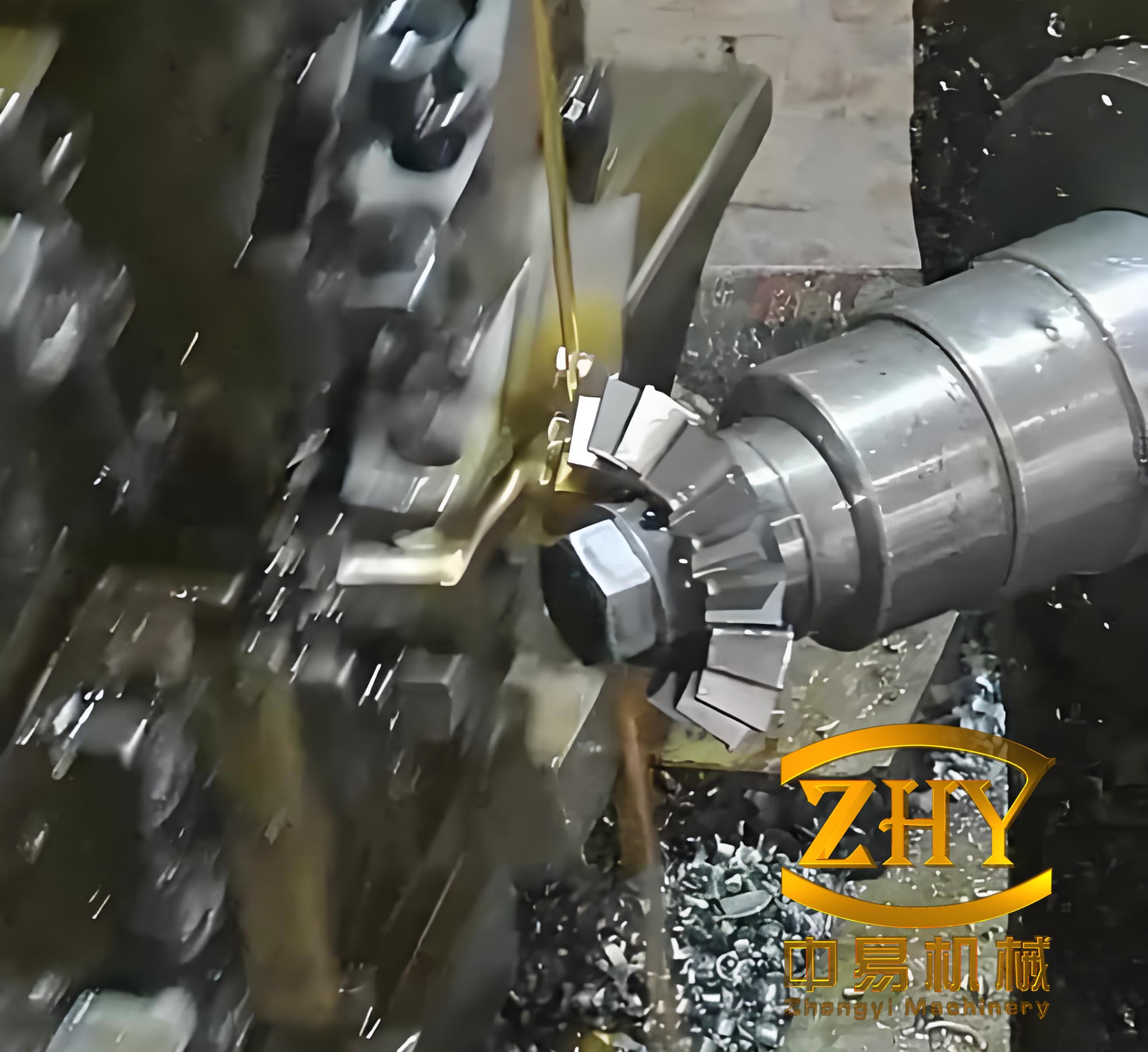
In practical applications, gear hobbing machines are used to implement this process. For large modified flexsplines, standard hobs may not suffice. Consider a flexspline with parameters: normal module $m_n = 0.5$ mm, modification coefficient $x = 3$, pressure angle $\alpha = 20^\circ$, number of teeth $z = 200$, tip diameter $d_a = 104$ mm, and root diameter $d_f = 101.65$ mm. A standard hob with $m_n = 0.5$ mm, $\alpha = 20^\circ$, $N = 1$, $Z_k = 12$, and outer diameter $D_h = 32$ mm is used. Simulation with 73 effective cutting edges and axial feed $f = 1.5$ mm/rev reveals significant errors near the tooth tip due to insufficient cutting edges. The hob’s pitch circle coincides with the gear’s pitch circle, but for large modifications, the gear’s pitch circle is smaller than the root circle, causing under-cutting. The minimum number of cutting edges required for complete tooth engagement is determined through simulation. For instance, at the tip diameter, left and right flanks require edges indexed up to 41 and -41, respectively, implying at least 83 effective edges for full cutting.
To overcome this, a new hob is designed based on the principle of equal base pitch between the hob and gear during gear hobbing. The goal is to shift the pitch circle to a more suitable location. First, an approximate pitch diameter $d’$ is calculated as the average of tip and root diameters:
$$ d’ = \frac{d_a + d_f}{2} $$
The pressure angle at this diameter is:
$$ \alpha_n’ = \arccos\left(\frac{d_b}{d’}\right) $$
where $d_b$ is the base diameter. This angle is rounded, and the precise pitch diameter is recalculated:
$$ d’ = \frac{d_b}{\cos \alpha_n’} $$
The normal module at the new pitch circle is:
$$ m_n’ = m_n \frac{\cos \alpha_n}{\cos \alpha_n’} $$
The new hob parameters are set as $m_{nh} = m_n’$ and $\alpha_{nh} = \alpha_n’$. The hob’s pitch diameter is:
$$ d_{nh} = D_h – (d’ – d_f) $$
The normal tooth thickness $S_{nh}$ on the hob is derived from the gear’s tooth thickness. The gear’s normal tooth thickness at the pitch circle $S_n$ is:
$$ S_n = \frac{\pi m_n}{2} + 2 x m_n \tan \alpha_n $$
At the new pitch circle, the tooth thickness becomes:
$$ S_n’ = S_n \frac{d’}{d} – d’ (\text{inv} \alpha_n’ – \text{inv} \alpha_n) $$
where $d$ is the gear’s pitch diameter, and $\text{inv}$ is the involute function. The hob’s normal tooth thickness is then:
$$ S_{nh} = \pi m_n’ – S_n’ $$
Other parameters, such as the hob’s outer diameter and number of gashes, remain unchanged. This new hob ensures that the gear hobbing process occurs at a pitch circle where tooth engagement is optimal, reducing the number of required cutting edges.
Simulations compare the performance of the standard and new hobs. For the new hob, the radial installation distance is adjusted to:
$$ a’ = \frac{d’ + d_{nh}}{2} $$
Results show that the new hob requires fewer cutting edges for complete tooth generation, as the pitch circle is now near the mid-height of the tooth. This allows for better utilization of the hob’s cutting edges across its length, enhancing efficiency and tool life in gear hobbing machines. The table below summarizes key parameters for both hobs:
| Parameter | Standard Hob | New Hob |
|---|---|---|
| Normal Module (mm) | 0.5 | 0.5143 |
| Normal Pressure Angle (°) | 20 | 24 |
| Pitch Diameter (mm) | 30.75 | 30.8878 |
| Normal Tooth Thickness (mm) | 0.7854 | 0.862 |
| Outer Diameter (mm) | 32 | 32 |
Error analysis focuses on helix and profile deviations. Helix deviations are evaluated at a constant radius along the tooth width. For axial feeds of 1.5 mm/rev, 1 mm/rev, and 0.5 mm/rev, the maximum helix errors with the standard hob are approximately 5.8 μm, 3.5 μm, and 0.6 μm, respectively. The new hob produces similar maximum errors but with a more uniform distribution along the tooth width. This uniformity is beneficial for gear hobbing machines as it reduces localized wear.
Profile deviations are assessed at specific tooth slots. For slots 1, 60, 120, and 180, with axial feed $f = 1$ mm/rev, the standard hob exhibits increasing errors toward the tooth tip, while the new hob maintains consistent errors across the profile. The table below compares profile errors at the tooth tip for selected slots:
| Tooth Slot | Standard Hob Error (μm) | New Hob Error (μm) |
|---|---|---|
| 1 | +8.2 | -0.5 |
| 60 | +9.1 | -0.6 |
| 120 | +10.3 | -0.4 |
| 180 | +7.9 | -0.5 |
Negative errors for the new hob indicate slight under-cutting, but the magnitude is smaller than the standard hob’s errors. The improved performance is due to the better alignment of the hob and gear geometries during gear hobbing.
In conclusion, gear hobbing of large modified flexsplines requires careful hob design to minimize errors. Standard hobs may lead to significant profile deviations due to insufficient cutting edges, but a customized hob based on equal base pitch principles can reduce these errors. The new hob allows for efficient use of cutting edges, prolonging tool life in gear hobbing machines. Future work could explore dynamic effects in gear hobbing processes or optimize hob geometries for specific applications. This research underscores the importance of precise tool design in achieving high-quality gear manufacturing.