
1. Definition and Calculation of Coincidence
The ratio between the length of the actual meshing line and the pitch of the base circle is called coincidence. As a condition for measuring the continuous transmission of involute gears, the coincidence degree should be satisfied ε ≥ 1, the greater the coincidence, the better the continuity and stability of the involute gear. In general machinery manufacturing, the allowable coincidence degree of involute gear transmission[ ε] ≈ 1.3~1.4, i.e. requirements ε ≥ [ ε]。
Where, B1B2 is the actual meshing line length; Pb is the pitch on the base circle, pb=π mcos α.
Calculation of coincidence degree
Wherein, Z1 and Z2 are the number of teeth of two meshing involute gears; α a 1、tan α A2 is the addendum pressure angle of two involute gears; α Is the engagement angle, and for involute gears with standard installation, α 20 °.
2. Analysis of meshing parameters
Next, the involute gear with a module of 4 and a tooth number of 30 is meshed with the involute gear with 60 teeth, 50 teeth, 40 teeth, 30 teeth, 17 teeth and 13 teeth respectively, and the meshing parameters are analyzed.
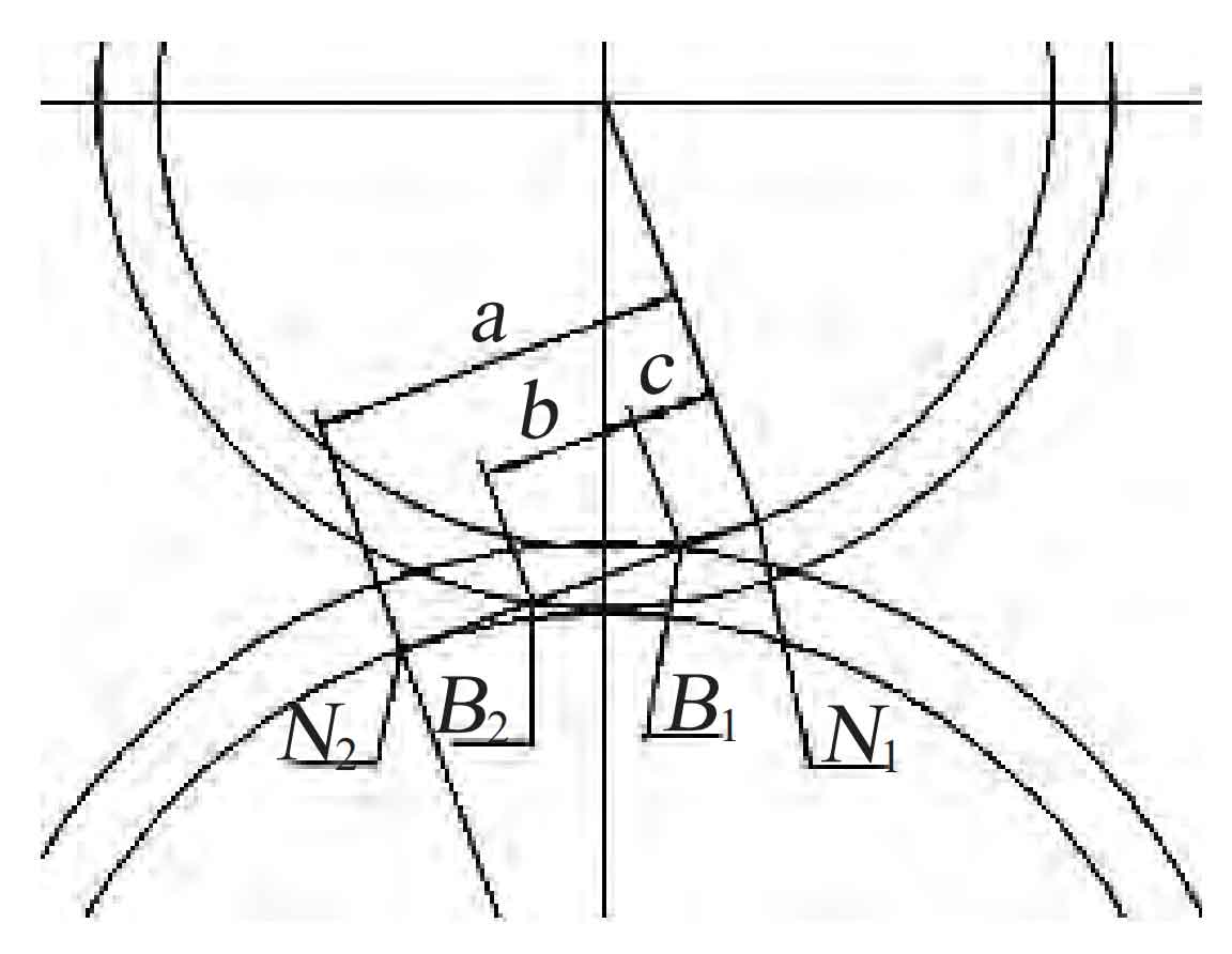
According to the base circle diameter, addendum circle diameter, indexing circle diameter, center distance and other parameters of each involute gear, draw the mesh diagrams of different combinations of 30 teeth/60 teeth, 30 teeth/50 teeth, 30 teeth/40 teeth, 30 teeth/30 teeth, 30 teeth/20 teeth, 30 teeth/17 teeth, 30 teeth/13 teeth, and count the three parameters a, b and c of each combination in the table, where a is the theoretical mesh line length and b is the actual mesh line length, C is the distance between the actual meshing starting point and the theoretical starting point.
| 30 teeth/60 teeth | 30 teeth/50 teeth | 30 teeth/40 teeth | 30 teeth/30 teeth | 30 teeth/20 teeth | 30 teeth/17 teeth | 30 teeth/13 teeth | |
| A (Theoretical meshing line length) | 61.6 | 54.7 | 47.9 | 41 | 34.2 | 32.1 | 29.4 |
| B (Distance between actual starting point and theoretical starting point) | 10 | 10.2 | 10.4 | 10.8 | 11.3 | 11.6 | 12 |
| C (Actual meshing line length) | 20.3 | 20.1 | 19.9 | 19.5 | 19 | 18.6 | 18.3 |
| Whether the actual meshing line is within the theoretical meshing line | Y | Y | Y | Y | Y | Y | N |
| Coincidence degree | 1.72 | 1.70 | 1.68 | 1.65 | 1.61 | 1.57 | — |
It can be seen from the data in the table that when a > b+c, root cutting will not occur; When a < b+c, undercutting occurs. The real reason for undercutting is that the actual meshing line exceeds the theoretical meshing line. With the reduction of the number of teeth, the more far the actual meshing starting point is from the theoretical meshing starting point, that is, the later it enters the meshing state, which leads to the reduction of the coincidence degree and the unstable transmission.