
The node velocity reflects the speed of metal flow at the node at a certain movement time. Figures (a), (b), (c) and (d) show the distribution of node deformation velocity when simulating steps 30, 45, 60 and 73 respectively.
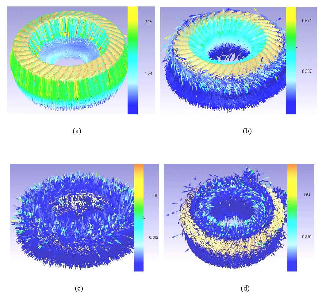
It can be seen from figure (a) that in the initial stage of the forming of the driven spiral bevel gear, since the crown part of the punch first contacts the blank, the metal flow speed at the forming part of the crown part of the spiral bevel gear blank is the fastest, and the metal flow speed at the contact part with the die is slow; In the mold filling stage, in step 30, as shown in figure (c), as the punch continues to press down, the metal of the gear teeth flows between the punch to quickly fill the tooth cavity; In the final filling stage, in step 73, as shown in figure (d), the tooth shape of the spiral bevel gear is filled and the metal stops flowing in the opposite direction. It can be seen from the simulation diagram that the metal in contact with the die is almost free of deformation. The forming is mainly concentrated in the gear teeth.