
According to the principle of elliptical arc tooth line cylindrical gear transmission, the formula for calculating the rotational speed of the driven wheel is obtained as follows:
In the formula, n1 is the speed of the driving wheel; Z1 and z2 represent the number of teeth on the driving and driven wheels, respectively.
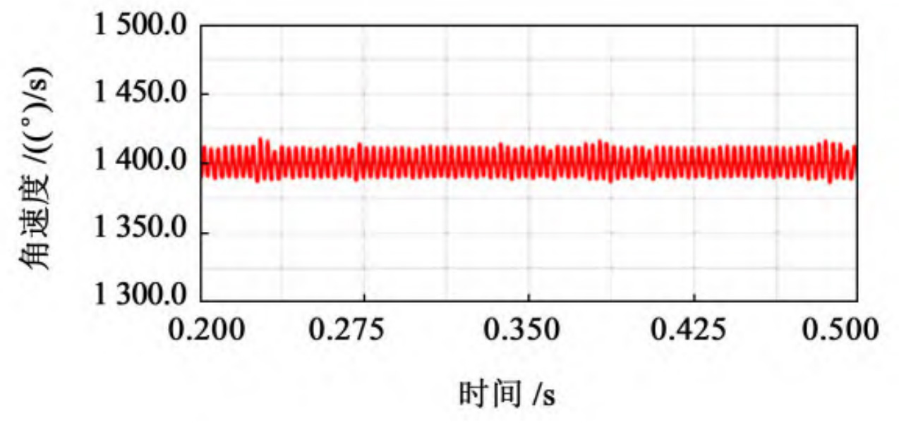
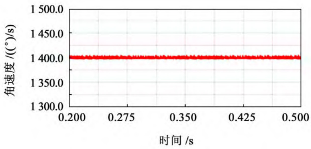
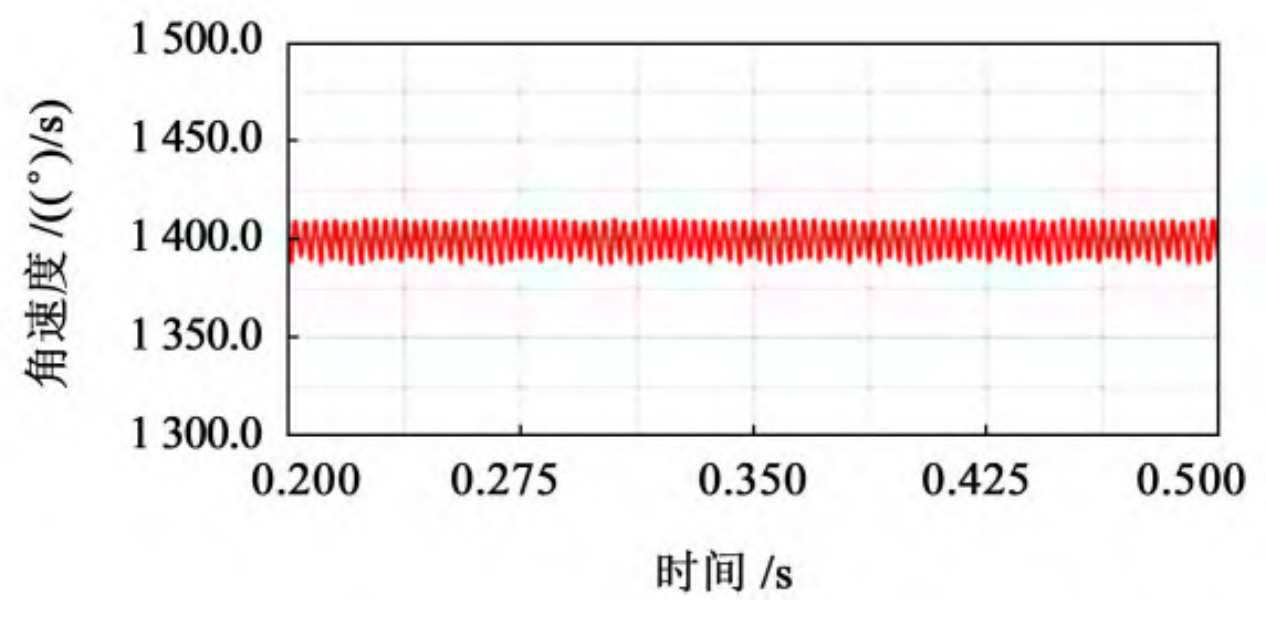
(a) Gear speed curve with RT=40 mm
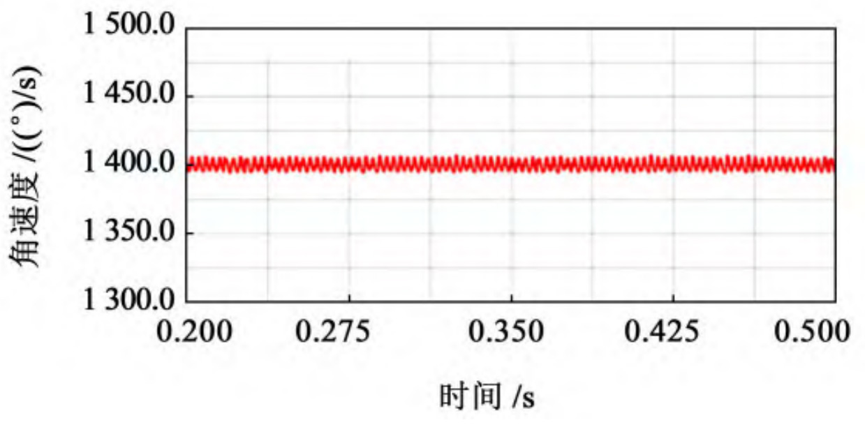
(b) Gear speed curve with RT=60 mm
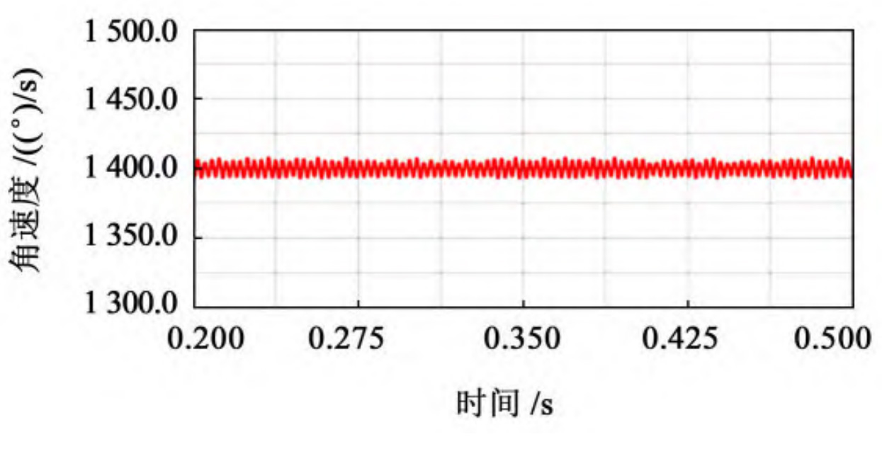
(c) Gear speed curve with RT=80 mm
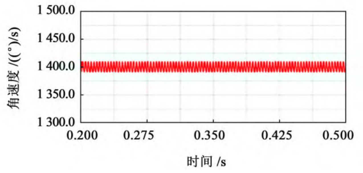
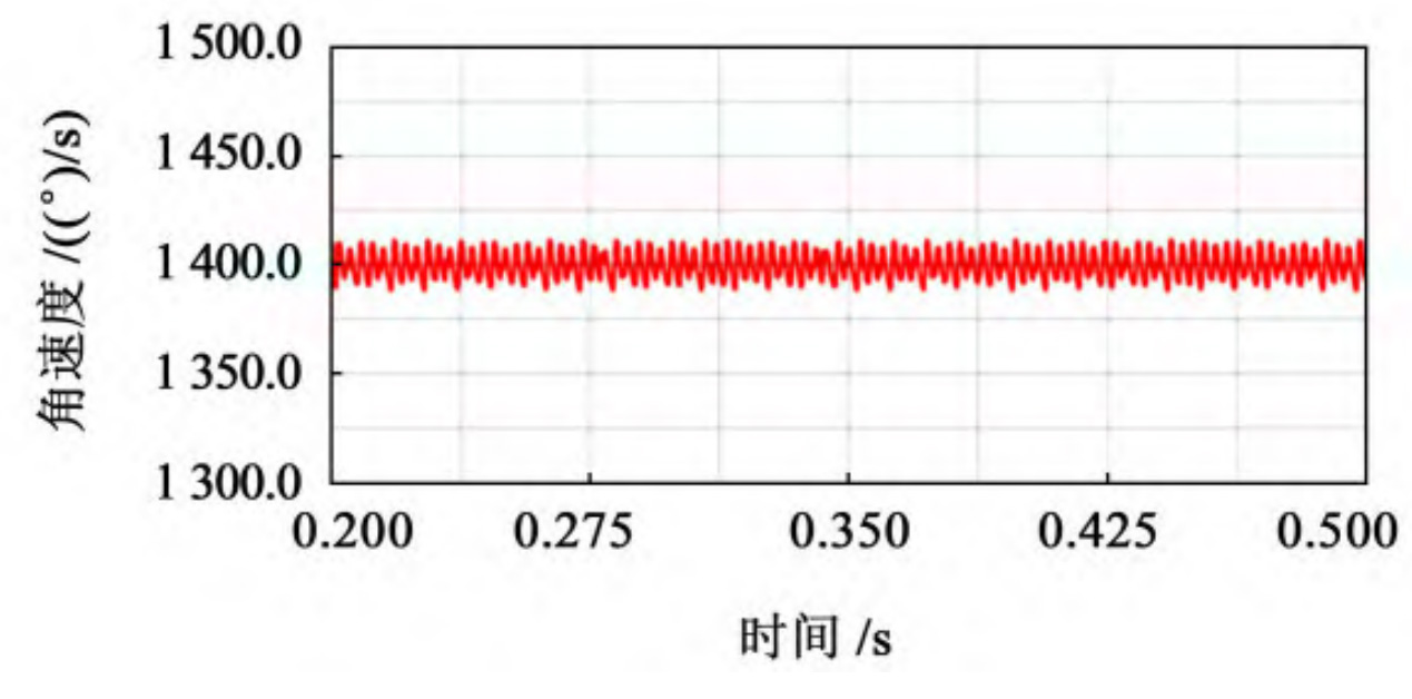
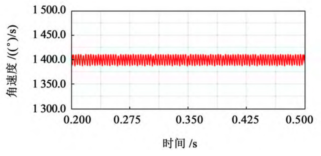
(d) Gear speed curve with RT=100 mm
(e) Gear speed curve with RT=120 mm
(f) Gear speed curve with RT=140 mm
(g) Gear speed curve with RT=160 mm
(h) Gear speed curve with RT=180 mm
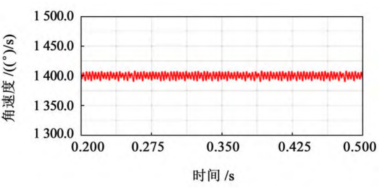
(i) Gear speed curve with RT=200 mm
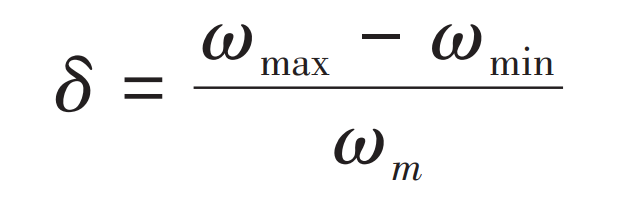
After calculation, the theoretical output speed of the driven wheel is 1400 (°)/s. After the simulation is completed, output the speed curve of the driven wheel’s speed over time, taking 0 The speed curve of the stable transmission stage from 2 to 0.5 seconds is obtained, and the speed variation curve of the driven wheel with different cutter radii is shown in Figure 1. Used for speed fluctuation coefficient δ Represents a value equal to the maximum value of angular velocity( ω Max) and the minimum value of angular velocity( ω The difference between min and the average value of angular velocity( ω m) The ratio of, expressed as:
According to the theoretical formula of speed fluctuation, extract the maximum, minimum, and average values of the driven wheel speed throughout the entire transmission process, and compare and analyze the data of elliptical arc tooth line cylindrical gears with different cutter radii, as shown in the table.
| Gear number | Knife head radius RT/mm | Maximum value of driven wheel speed/(°)/s) | Minimum value of driven wheel speed/(°)/s) | Average value of driven wheel speed/(°)/s) | Fluctuation coefficient of driven wheel speed/(°)/s) |
| 1 | 30 | 1 415. 213 | 1 386. 836 | 1 401. 025 3 | 0.020 254 45 |
| 2 | 40 | 1 416. 261 | 1 386. 389 | 1 401. 325 2 | 0.021 316 97 |
| 3 | 50 | 1 416. 366 | 1 385. 722 | 1 401. 044 4 | 0.021 872 26 |
| 4 | 60 | 1 413. 765 | 1 390. 539 | 1 402. 152 0 | 0.016 564 54 |
| 5 | 70 | 1 410. 329 | 1 396. 523 | 1 403. 426 1 | 0.009 837 35 |
| 6 | 80 | 1 405. 925 | 1 395. 785 | 1 400. 855 5 | 0.007 238 43 |
| 7 | 90 | 1 404. 627 | 1 394. 847 | 1 399. 737 5 | 0.006 987 02 |
| 8 | 100 | 1 404. 562 | 1 396. 622 | 1 400. 592 5 | 0.005 669 03 |
| 9 | 110 | 1 406. 532 | 1 397. 386 | 1 401. 959 5 | 0.006 524 73 |
| 10 | 120 | 1 404. 682 | 1 395. 931 | 1 400. 307 1 | 0.006 249 34 |
| 11 | 130 | 1 409. 561 | 1 399. 256 | 1 404. 408 6 | 0.007 337 61 |
| 12 | 140 | 1 407. 760 | 1 395. 658 | 1 401. 709 7 | 0.008 633 74 |
| 13 | 150 | 1 415. 732 | 1 393. 673 | 1 404. 703 0 | 0.015 703 68 |
| 14 | 160 | 1 413. 519 | 1 389. 249 | 1 401. 384 4 | 0.017 318 59 |
| 15 | 170 | 1 417. 169 | 1 393. 002 | 1 405. 086 0 | 0.017 199 66 |
| 16 | 180 | 1 417. 454 | 1 390. 137 | 1 403. 796 1 | 0.019 459 38 |
| 17 | 190 | 1 418. 493 | 1 386. 985 | 1 402. 739 5 | 0.022 461 76 |
| 18 | 200 | 1 419. 987 | 1 389. 014 | 1 404. 500 8 | 0.022 052 68 |
Based on the measured maximum, minimum, and average values of the rotational speed, and the calculation formula for the speed fluctuation coefficient, the speed fluctuation coefficient of the driven wheel of the elliptical arc tooth line cylindrical gear can be calculated under different cutter radii. The relevant curves of the velocity fluctuation of the driven wheel under different cutter radii are fitted as shown in Figure 2, from which the experimental data can be observed.
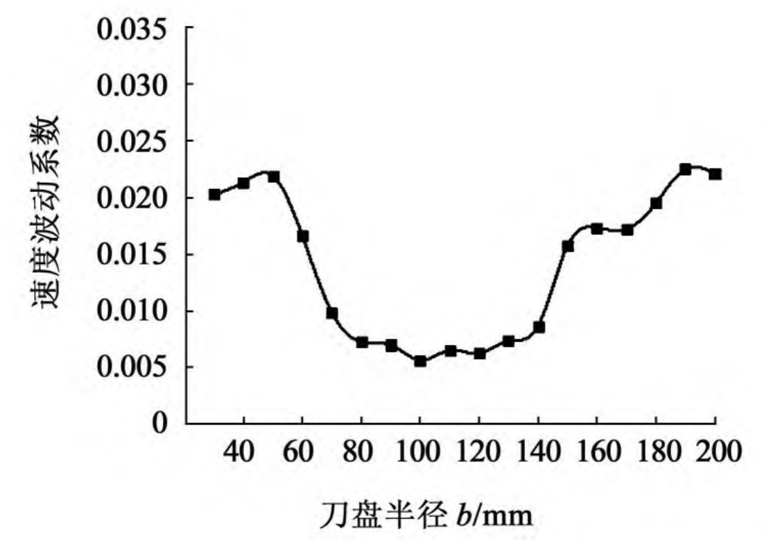
From Figure 2, it can be seen that as the radius of the cutter head gradually increases, the speed fluctuation coefficient of the driven wheel of the elliptical arc tooth line cylindrical gear first increases and then decreases, then tends to be gentle, and finally gradually increases. Among them, when the radius of the cutterhead is 1 When 34b ≤ RT ≤ 2.34b, where b is the tooth width of the elliptical arc tooth line cylindrical gear, the transmission stability of the elliptical arc tooth line cylindrical gear pair within this range reaches the optimal state; In other intervals, relative speed fluctuations are relatively large, and operational stability may be affected, with a maximum fluctuation coefficient of 0 022 5, but it can still be used in working conditions such as automotive gearboxes.
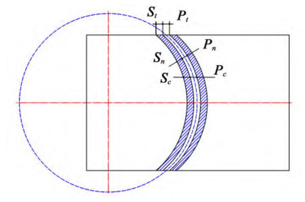
(a) Tooth line shape when the cutter head radius is too small
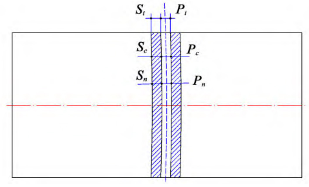
(b) Tooth line shape when the cutter head radius is too large
Regarding the possible causes of this phenomenon, research and analysis show that when the radius of the cutter head is in a small range, as shown in Figure 3 (a), the elliptical arc tooth line is more prominent, and the circumferential thickness of the gear teeth is equal everywhere. However, the normal thickness on both sides of the gear teeth is much smaller than the normal thickness in the middle of the gear teeth, resulting in poor rigidity on both sides of the gear teeth and poor transmission stability of the elliptical arc tooth line cylindrical gear; When the cutter head is at a larger radius, as shown in Figure 3 (b), the elliptical arc tooth line is close to the straight tooth, and the performance of the elliptical arc tooth line gear is similar to that of the straight cylindrical gear in all aspects. Therefore, in order to ensure the stability of elliptical arc tooth line cylindrical gear transmission, improve the load-bearing capacity of elliptical arc tooth line cylindrical gear, and control the speed fluctuation of gear transmission, it is necessary to control the machining tool radius, i.e. the short half axis of elliptical arc tooth line, to 1 Within the range of 34b ≤ RT ≤ 2. 34b.