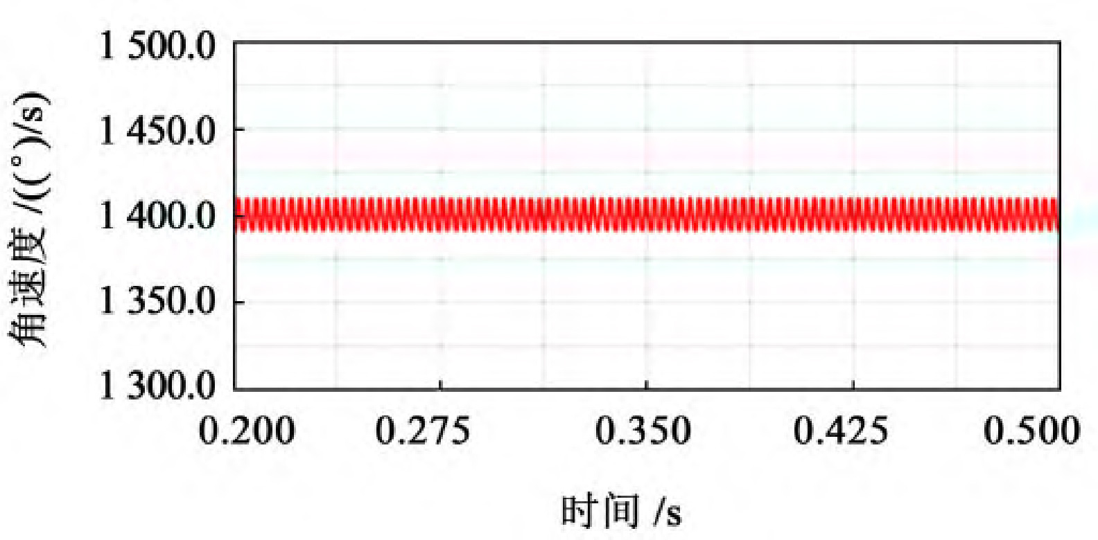
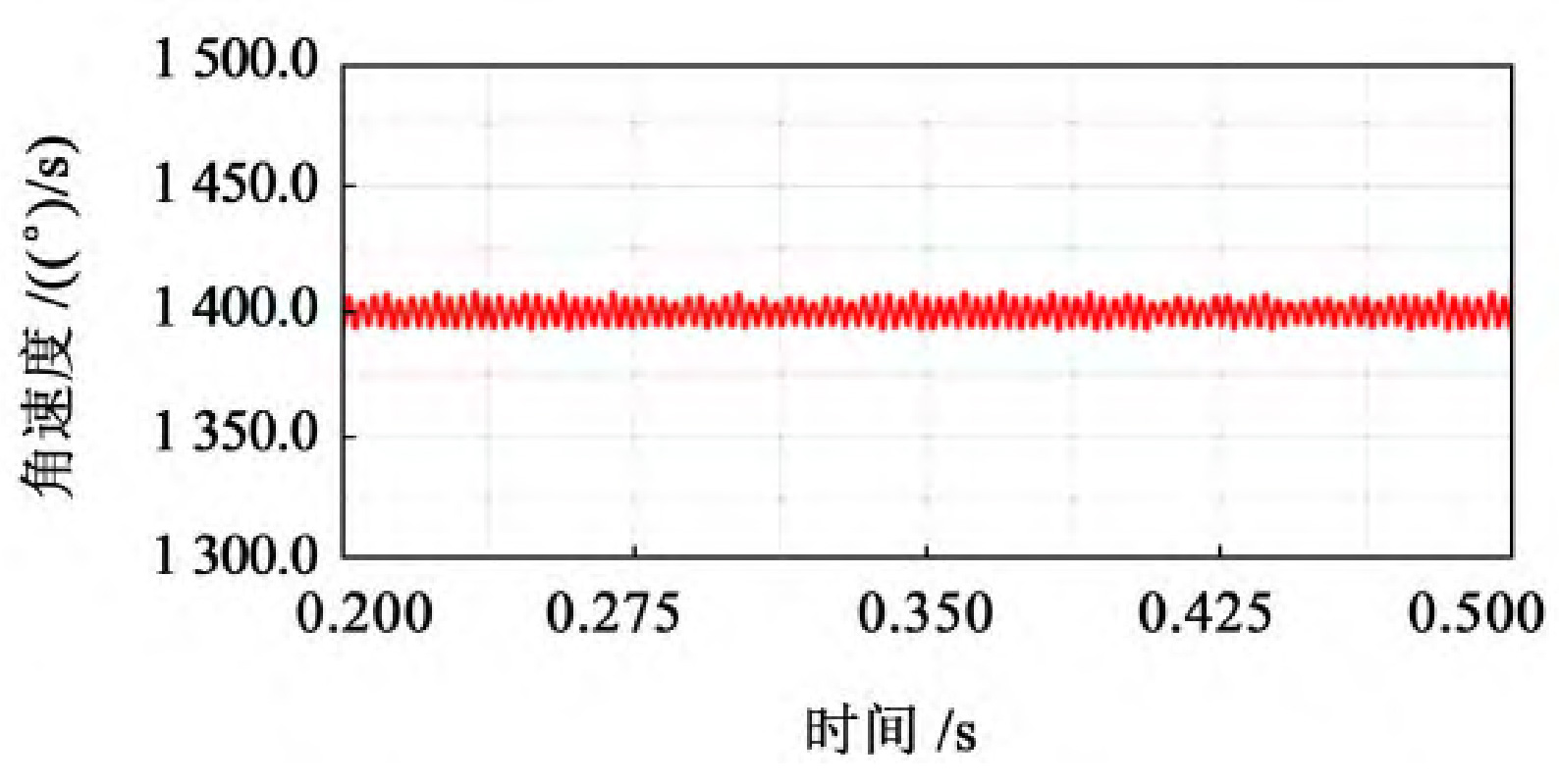
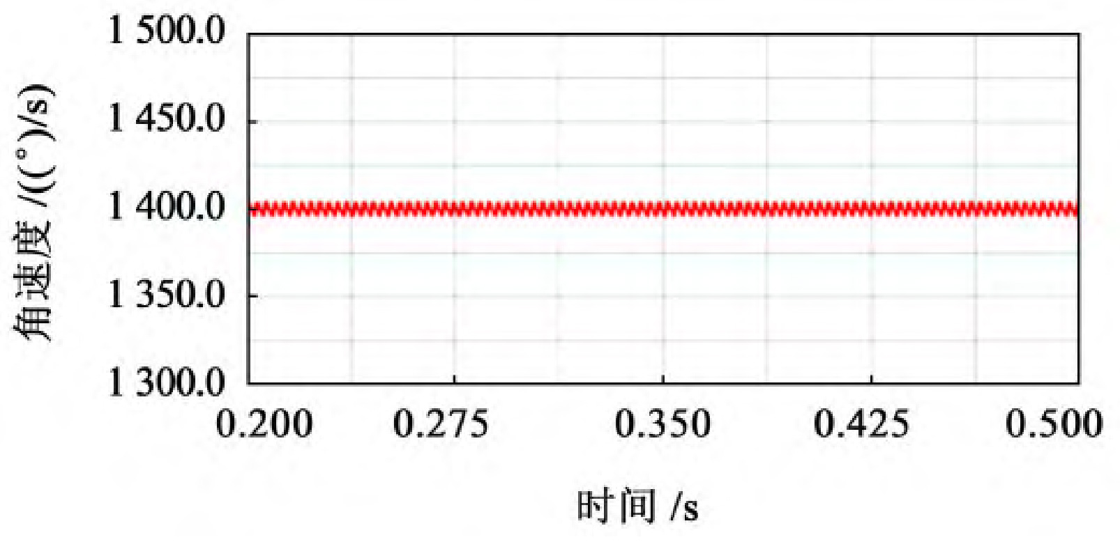
As shown in Figure 1, select the stable output speed curve, which is 0 2~0.5 s operating interval.
(a) Gear speed curve with b=40 mm
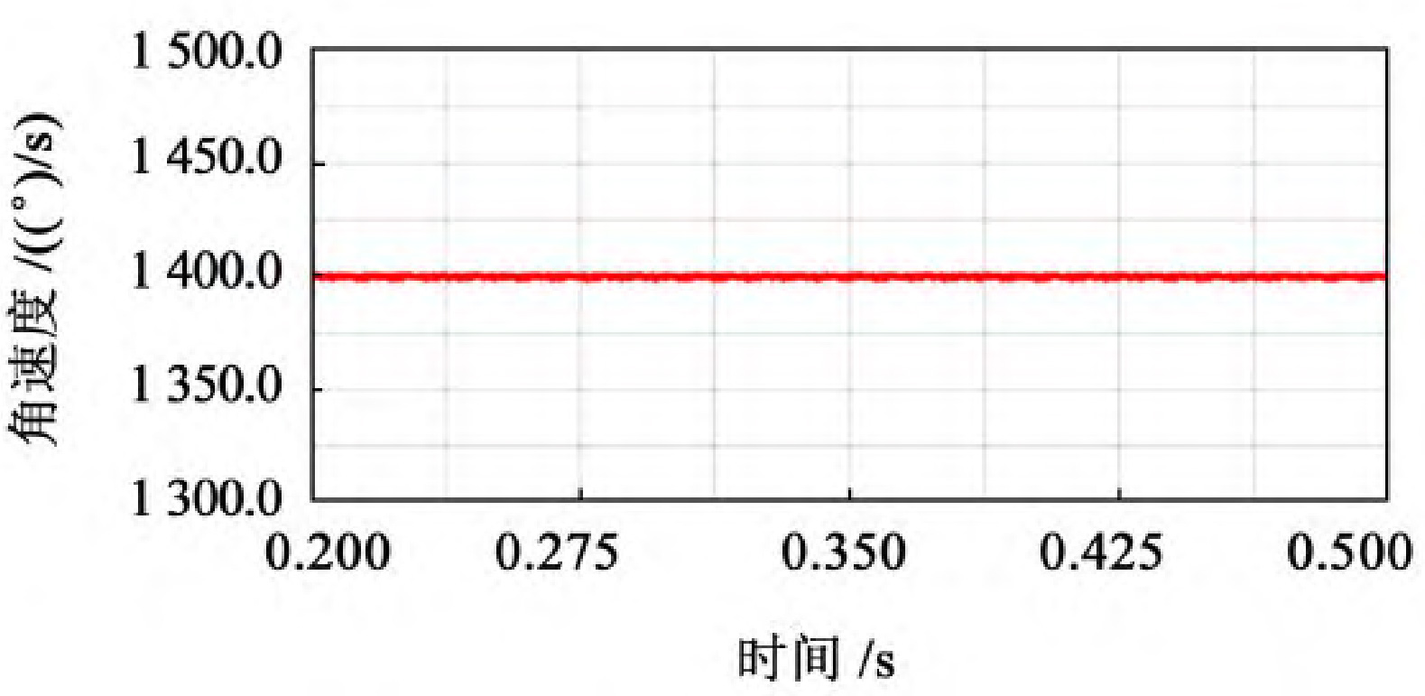
(b) Gear speed curve with b=50 mm
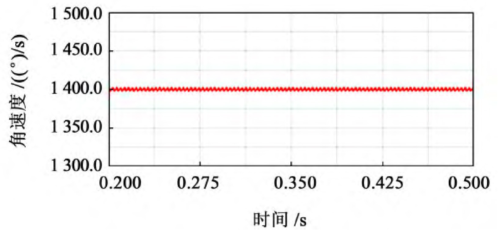
(c) Gear speed curve with b=60 mm
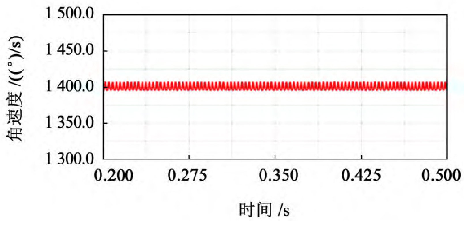
(d) Gear speed curve with b=70 mm
(e) Gear speed curve with b=80 mm
(f) Gear speed curve with b=90 mm
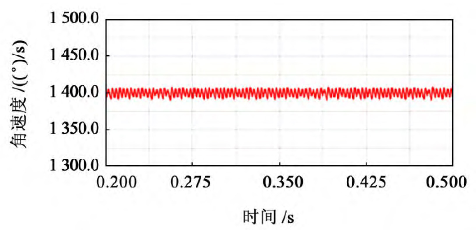
(g) Gear speed curve with b=100 mm
From Figure 1, it can be seen that the trend of the speed curve of the driving wheel fluctuates around a certain value and shows periodic changes. From the experimental data, it can be seen that when 40 mm ≤ b<60 mm, the fluctuation amplitude of the driven wheel speed is relatively large, with a fluctuation range of 1380-1420, and the speed fluctuation is relatively large; When 60 mm ≤ b ≤ 80 mm, the fluctuation range of the driven wheel speed is relatively small, ranging from 1395 to 1405, and the transmission is relatively stable; When b>80 mm, the fluctuation amplitude of the driven wheel speed shows an upward trend.
According to the theoretical formula of speed fluctuation, the maximum, minimum, and average values of the driven wheel speed at each tooth width are shown in the table.
| Tooth width b/mm | Maximum speed/(°)/s | Minimum speed/(°)/s | Average speed/(°)/s | Speed fluctuation coefficient δ |
| 40 | 1 409. 129 4 | 1 391. 603 2 | 1 400. 366 3 | 0.012 515 4 |
| 50 | 1 407. 524 1 | 1 395. 301 9 | 1 401. 413 0 | 0.008 721 3 |
| 60 | 1 402. 501 2 | 1 398. 310 9 | 1 400. 406 5 | 0.002 992 2 |
| 70 | 1 401. 425 7 | 1 398. 699 3 | 1 400. 062 5 | 0.001 947 3 |
| 80 | 1 402. 256 1 | 1 398. 706 3 | 1 400. 481 2 | 0.002 534 7 |
| 90 | 1 407. 752 9 | 1 395. 384 5 | 1 401. 568 7 | 0.008 824 7 |
| 100 | 1 408. 269 1 | 1 394. 398 7 | 1 401. 333 9 | 0.009 898 0 |
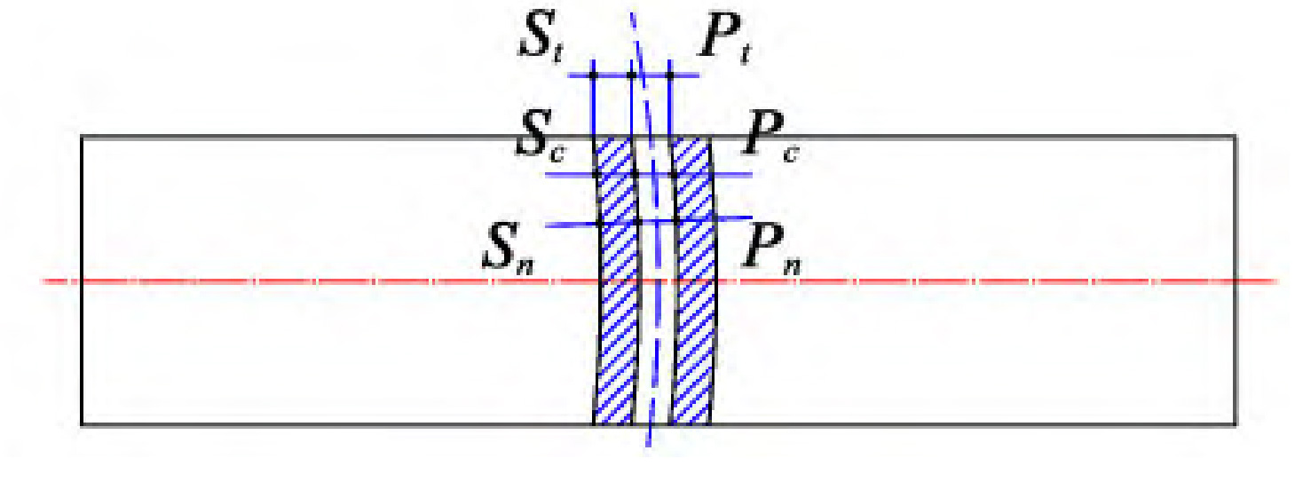
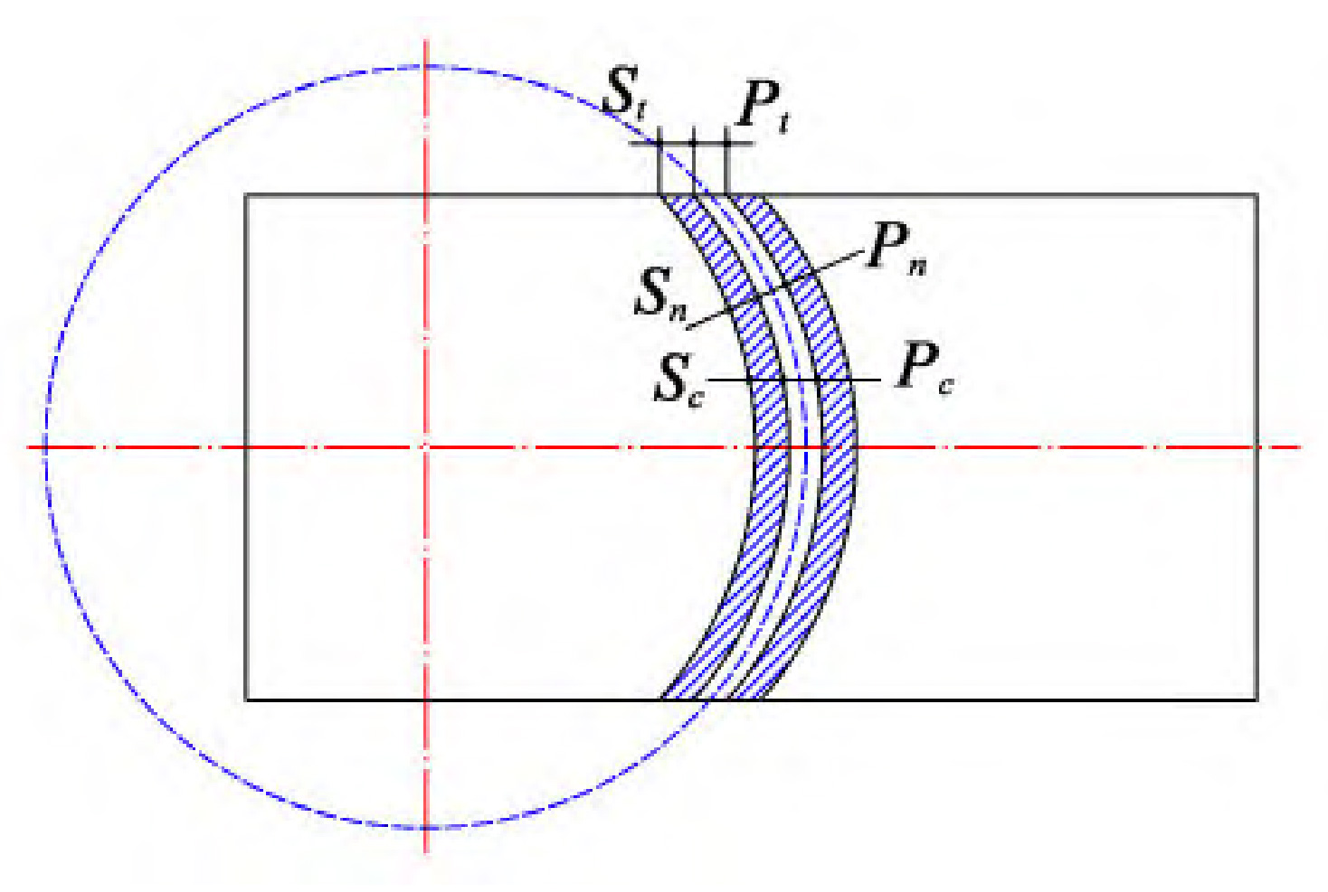
Calculate the speed fluctuation coefficient of each elliptical arc tooth line cylindrical gear group transmission based on the theoretical formula of speed fluctuation δ, Fill in Table 4 and use the velocity fluctuation coefficient as the vertical coordinate and the elliptical arc tooth line cylindrical gear tooth width as the horizontal coordinate. Draw each point in the coordinate system and fit it into a smooth curve, reflecting the trend of velocity fluctuation, as shown in Figure 2.
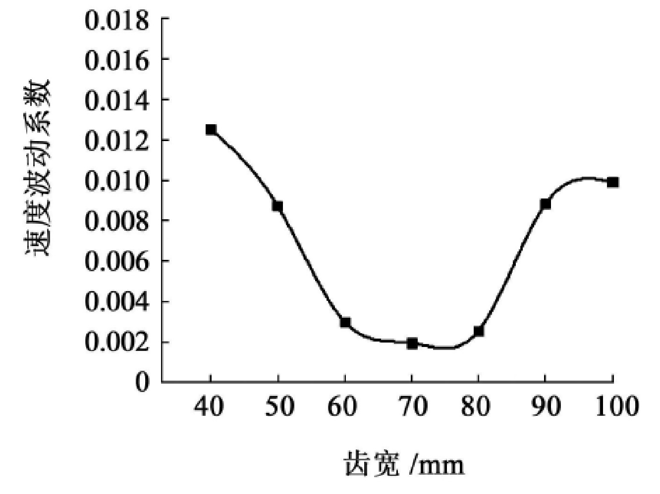
As shown in Figure 2, the fluctuation of the driven wheel speed shows a trend of slowly decreasing, then stabilizing, and then rapidly increasing as the tooth width gradually increases. The smoothness of the transmission deteriorates with the increase of the speed fluctuation coefficient, thus reducing the range of tooth width to 0 When 6RT ≤ b ≤ 0.8RT, the speed fluctuation coefficient of the elliptical arc tooth line cylindrical gear pair transmission within the range is small, and the specific tooth width value should be determined according to the specific working conditions. Further research on this phenomenon reveals that, as shown in Figure 3 (a), due to the small tooth width, the tooth line advantages of elliptical arc gears cannot be fully demonstrated, and their performance in all aspects is close to that of straight cylindrical gears; As shown in Figure 3 (b), when the tooth width is large, the tooth line of the elliptical arc gear is too prominent, causing the normal thickness on both sides of the gear teeth to be much smaller than the normal thickness in the middle of the gear teeth, resulting in poor rigidity of the gear teeth and affecting transmission stability.