
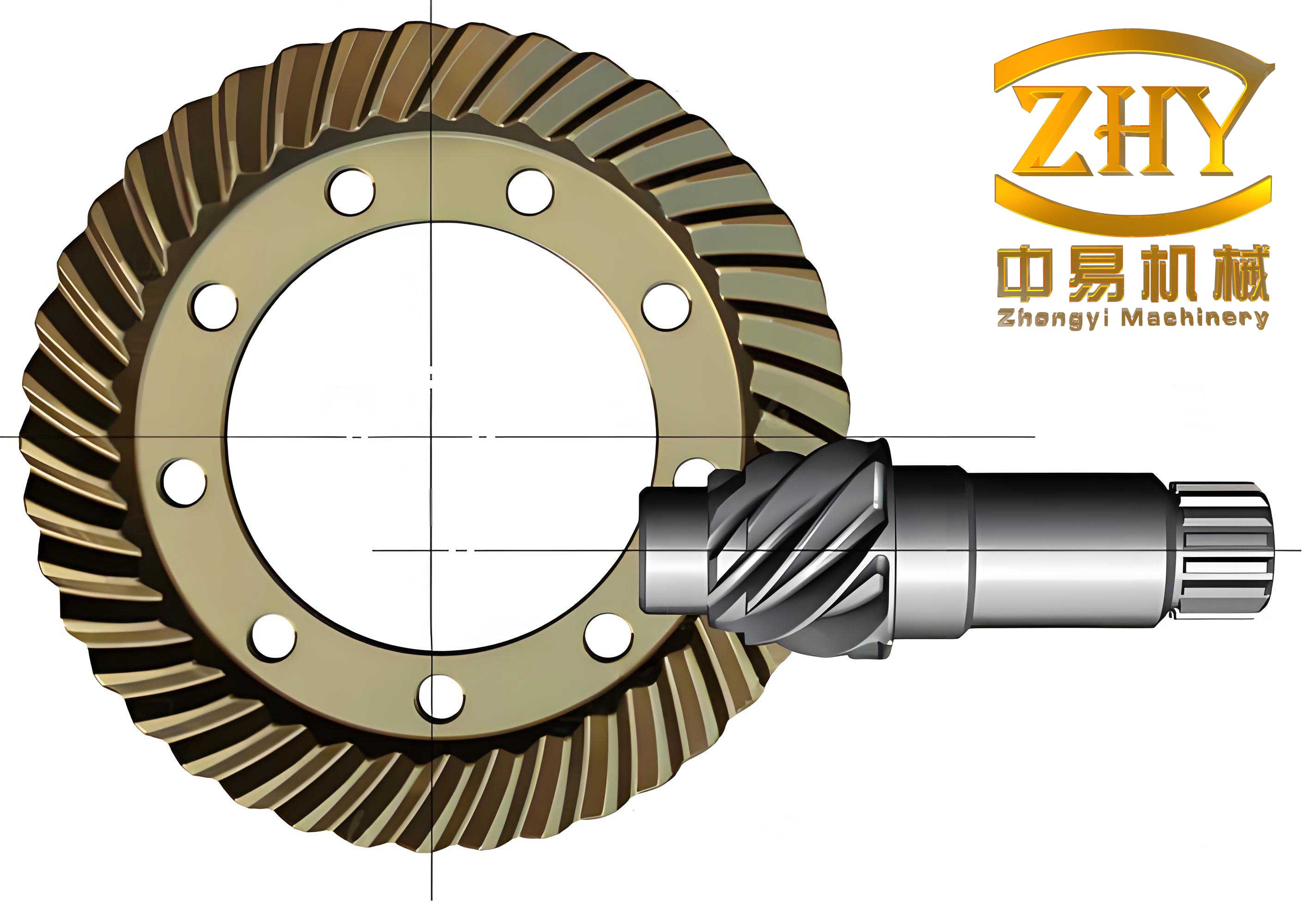
In the field of mechanical transmission systems, hypoid gears play a critical role due to their ability to transmit motion and power between non-intersecting axes with high efficiency, smooth operation, and substantial load-carrying capacity. As a researcher focused on tribology and gear dynamics, I have extensively studied the lubrication performance of hypoid gears, particularly under heavy-load conditions commonly encountered in applications such as aerospace engines, helicopters, and heavy-duty trucks. The performance and service life of these gears are directly influenced by the lubrication state at the tooth interface, where inadequate lubrication can lead to failures like pitting, scuffing, wear, and cracking. This article presents a comprehensive analysis based on a unified lubrication model developed for hypoid gears, incorporating factors like contact geometry, the oblique angle between entrainment velocity and the principal axis of the contact ellipse, and lubricant rheological properties. Through numerical simulations, I investigate the evolution of oil film thickness, pressure, flash temperature, and von Mises stress during the entire engagement process from mesh-in to mesh-out under heavy loads. Additionally, I explore the impact of pinion rotational speed on lubrication performance, providing insights for optimizing hypoid gear operation.
Hypoid gears are widely used in various high-performance transmission systems due to their unique geometric characteristics, which allow for offset axes and higher torque transmission compared to conventional bevel or spiral gears. However, the complex geometry and meshing behavior of hypoid gears make their lubrication analysis more challenging than that for spur or helical gears. Traditional lubrication models often simplify the contact as line or point contacts with aligned entrainment velocities, but for hypoid gears, the entrainment velocity vector is not aligned with the minor axis of the contact ellipse, leading to asymmetric pressure and film thickness distributions. This misalignment must be accounted for to accurately predict lubrication performance, especially under heavy loads where elastohydrodynamic lubrication (EHL) effects dominate. In this study, I address these complexities by developing a full numerical solution for the mixed EHL in elliptical contacts with an arbitrary entrainment angle, extending previous work on gear lubrication.
The lubrication model for hypoid gears is built upon the fundamental equations governing elastohydrodynamic lubrication. The Reynolds equation, which describes fluid flow in the thin film between contacting surfaces, is modified to include the oblique entrainment angle characteristic of hypoid gears. For an elliptical contact where the entrainment velocity $u_e$ makes an angle $\theta$ with the x-axis (aligned with the minor axis of the ellipse), the Reynolds equation in dimensionless form can be expressed as:
$$\frac{\partial}{\partial X}\left(\frac{\bar{\rho} H^3}{\bar{\eta}} \frac{\partial P}{\partial X}\right) + \frac{\partial}{\partial Y}\left(\frac{\bar{\rho} H^3}{\bar{\eta}} \frac{\partial P}{\partial Y}\right) = \frac{\partial (\bar{\rho} H)}{\partial X} \cos\theta + \frac{\partial (\bar{\rho} H)}{\partial Y} \sin\theta$$
Here, $P$ is the dimensionless pressure, $H$ is the dimensionless film thickness, $\bar{\rho}$ is the dimensionless density, $\bar{\eta}$ is the dimensionless viscosity, and $X$ and $Y$ are dimensionless coordinates scaled by the semi-minor axis $a$ of the Hertzian contact ellipse. The film thickness equation accounts for the geometry of the contacting surfaces and elastic deformation:
$$H(X, Y, T) = H_0(T) + \frac{X^2}{2R_X} + \frac{Y^2}{2R_Y} + \frac{2}{\pi} \int_{-\infty}^{\infty} \int_{-\infty}^{\infty} \frac{P(\xi, \zeta) \, d\xi \, d\zeta}{\sqrt{(X – \xi)^2 + (Y – \zeta)^2}}$$
where $H_0$ is the central film thickness, $R_X$ and $R_Y$ are the reduced radii of curvature in the x and y directions, and the integral term represents the elastic deformation $V(x,y)$ calculated using the Boussinesq influence function. The pressure-viscosity and pressure-density relationships for the lubricant are given by the Barus and Dowson-Higginson equations, respectively:
$$\bar{\eta} = \exp\left(\alpha p\right) \quad \text{and} \quad \bar{\rho} = 1 + \frac{0.6 \times 10^{-9} p}{1 + 1.7 \times 10^{-9} p}$$
where $\alpha$ is the pressure-viscosity coefficient, and $p$ is the pressure in Pa. These equations are critical for modeling the non-Newtonian behavior of lubricants under high pressures typical in hypoid gear contacts.
The contact geometry and kinematics for hypoid gears are derived from gear meshing theory. The relative velocity $V_{12}$ and entrainment velocity $V_{1+2}$ at the contact point are calculated based on the pinion and gear rotational speeds, tooth geometry, and offset distance. For a hypoid gear pair with pinion speed $\omega_1$, pinion tooth count $n$, gear tooth count $N$, and position vectors $R_{bl}$ and $R_{br}$ from the pinion and gear axes, the velocities are:
$$V_{12} = \omega_1 (p_l \times R_{bl}) + \frac{n}{N} \omega_1 (p_r \times R_{br})$$
$$V_{1+2} = \omega_1 (p_l \times R_{bl}) – \frac{n}{N} \omega_1 (p_r \times R_{br})$$
where $p_l$ and $p_r$ are unit vectors along the pinion and gear axes. The curvature parameters, including principal curvatures and twist, are computed at each meshing point to determine the elliptical contact dimensions. The orientation angle $\tau$ between the major axis of the contact ellipse and the x-direction is essential for aligning the coordinate system in the lubrication model.
To solve the coupled system of equations, I employ a semi-system approach that combines the Reynolds equation, film thickness equation, and load balance equation. The elastic deformation is efficiently computed using the discrete convolution and fast Fourier transform (DC-FFT) method, which reduces computational cost. The numerical domain is discretized into a grid of 256 × 256 points, with normalized coordinates ranging from -3 to 2 in the x-direction and -2 to 2 in the y-direction to capture the entire contact area. The solution iterates until convergence is achieved for pressure and film thickness distributions under the applied load.
For flash temperature analysis, I integrate a thermal model that accounts for frictional heating at the contact interface. The flash temperature rise is calculated using a moving heat source approach, where the heat flux is derived from the shear stress in the lubricant film. The equations for surface temperatures $T_1$ and $T_2$ on the pinion and gear, respectively, are given by Volterra integral equations:
$$T_1(\xi) = T_{b1} + \frac{1}{\sqrt{\pi \rho_1 C_1 u_1 k_1}} \int_{-\infty}^{\xi} \frac{k_f [T_2(\lambda) – T_1(\lambda)] + q(\lambda)}{\sqrt{\xi – \lambda}} d\lambda$$
$$T_2(\xi) = T_{b2} + \frac{1}{\sqrt{\pi \rho_2 C_2 u_2 k_2}} \int_{-\infty}^{\xi} \frac{k_f [T_1(\lambda) – T_2(\lambda)] + q(\lambda)}{\sqrt{\xi – \lambda}} d\lambda$$
where $T_{b1}$ and $T_{b2}$ are bulk temperatures, $\rho$, $C$, and $k$ are density, specific heat, and thermal conductivity, $u$ is surface velocity, $k_f$ is the thermal conductivity of the lubricant, and $q$ is the heat flux due to sliding friction. This model allows for predicting surface temperatures that can lead to scuffing failures in hypoid gears.
The subsurface stress field, particularly the von Mises stress, is computed from the pressure and shear traction distributions using influence coefficients. The von Mises stress $\sigma_{vM}$ at depth $z$ is given by:
$$\sigma_{vM}(x,y,z) = \sqrt{\frac{1}{2} \left[ (\sigma_{xx} – \sigma_{yy})^2 + (\sigma_{yy} – \sigma_{zz})^2 + (\sigma_{zz} – \sigma_{xx})^2 + 6(\tau_{xy}^2 + \tau_{yz}^2 + \tau_{zx}^2) \right]}$$
where the stress components $\sigma_{ij}$ and $\tau_{ij}$ are obtained by convolving the surface tractions with appropriate Green’s functions. This analysis helps identify regions of high stress that may initiate fatigue cracks.
In this study, I consider a hypoid gear pair from an automotive rear axle as a case study. The gear parameters are summarized in Table 1, and the machining settings are listed in Table 2. The pinion input speed is varied from 500 to 3000 rpm, with an input torque of 139 N·m, representing heavy-load conditions. The load distribution along the path of contact is derived from prior gear analysis, with load sharing coefficients $\epsilon$ indicating the fraction of total load carried at each meshing point.
| Parameter | Pinion | Gear |
|---|---|---|
| Number of Teeth | 12 | 47 |
| Outer Diameter (mm) | 85.6 | 205.88 |
| Face Width (mm) | 36 | 31.75 |
| Spiral Angle | 50° | 27°54′ |
| Hand of Spiral | Left | Right |
| Mean Pressure Angle | 19°00′ | 19°00′ |
| Offset Distance (mm) | 35 | 35 |
| Shaft Angle | 90° | 90° |
| Parameter | Pinion (Concave-Outer Tool) | Gear (Convex-Inner Tool) |
|---|---|---|
| Cutter Diameter (mm) | 181.86 | 190.5 – 2.03 |
| Tool Angle | 10°00′ | 14°00′ |
| Machine Root Angle | 15°37′ | 67°02′ |
| Cradle Angle | -157°46′ | -14°47′ |
| Eccentric Angle | 30°25′ | 30°28′ |
| Bed Position (mm) | 6.32 | 4.25 |
| Ratio of Roll | 3.844 | 0.998 |
| Blank Offset (mm) | 30.69 | -5.81 |
The material properties for the hypoid gears are: elastic modulus $E = 2.078 \times 10^{11}$ Pa, Poisson’s ratio $\nu = 0.3$. The lubricant properties are: initial viscosity $\eta_0 = 0.095$ Pa·s, pressure-viscosity coefficient $\alpha = 1.82 \times 10^{-8}$ Pa$^{-1}$, and ambient density $\rho_0 = 870$ kg/m$^3$. These parameters are used in the numerical simulations to analyze lubrication performance.
The results from the numerical analysis reveal significant insights into the lubrication behavior of hypoid gears under heavy loads. During the engagement process from mesh-in to mesh-out, the contact point moves along the tooth flank, and the entrainment velocity magnitude and angle change accordingly. Figure 4 shows the entrainment velocity $u_e$ as a function of meshing position, indicating variations that affect film formation. The maximum Hertzian pressure at each contact point, plotted in Figure 5, reaches up to 1.32 GPa, confirming the heavy-load condition.
The pressure and film thickness distributions at three representative meshing points (with entrainment angles $\theta = 0^\circ$, $17.5^\circ$, and $35^\circ$) are illustrated in Figures 6 and 7. Due to the oblique entrainment angle, the pressure distribution is asymmetric about the x-axis, with the asymmetry becoming more pronounced near the mesh-out point. The film thickness distribution similarly shows skewness, with thinner films on the trailing edge of the contact ellipse. This asymmetry is a key characteristic of hypoid gear lubrication and must be considered in design.
The flash temperature distributions at the same meshing points are shown in Figure 8. The maximum flash temperature occurs near the contact center, where pressures are highest, and the distribution is influenced by the sliding velocity vector. As the meshing point progresses, the flash temperature initially increases, peaks around mid-engagement, and then decreases toward mesh-out. This trend is attributed to the combined effects of pressure, film thickness, and sliding speed variations along the path of contact.
The subsurface von Mises stress distributions, depicted in Figure 9, indicate that the maximum stress is not at the surface but at a certain depth below it, typically around 0.3 to 0.5 times the semi-minor axis $a$. This subsurface stress concentration is critical for fatigue life prediction, as it can initiate pitting or spalling failures in hypoid gears. The maximum von Mises stress decreases monotonically from mesh-in to mesh-out, following the pressure trend.
To quantify these trends, I summarize the central film thickness $h_c$, maximum von Mises stress $\sigma_{vM,max}$, and maximum flash temperature $T_{f,max}$ during the engagement process in Figure 10. The central film thickness increases monotonically, while the maximum von Mises stress decreases monotonically. The maximum flash temperature shows a non-monotonic behavior, rising to a peak before declining. These patterns highlight the complex interplay between geometry, kinematics, and lubrication in hypoid gears.
A critical factor influencing lubrication performance is the rotational speed of the pinion. I analyze the effects of pinion speed at 500, 1000, and 3000 rpm, keeping other parameters constant. The results, plotted in Figure 11, demonstrate that speed has a profound impact on film thickness and flash temperature. At 3000 rpm, the central film thickness is highest, providing better separation of surfaces. As speed decreases to 500 rpm, the film thickness reduces significantly, with values as low as 130 nm at the mesh-in point. Given that hypoid gears typically have surface roughness on the order of micrometers, such thin films indicate a mixed lubrication regime where asperity contact occurs, increasing the risk of wear due to sliding friction.
Conversely, higher speeds lead to elevated flash temperatures due to increased sliding velocities. At 3000 rpm, the maximum flash temperature can exceed safe limits, potentially causing scuffing or thermal degradation of the lubricant. Thus, there is a trade-off: low speeds reduce film thickness and promote wear, while high speeds increase temperatures and promote scuffing. To optimize hypoid gear performance, it is essential to select an operating speed that balances these factors, possibly through advanced lubrication strategies or material coatings.
The implications of this study extend to practical applications. For instance, in helicopter transmissions, hypoid gears operate under varying loads and speeds, and understanding lubrication mechanisms can inform maintenance schedules and design improvements. By incorporating the oblique entrainment angle into lubrication models, engineers can more accurately predict film thickness and pressure distributions, leading to better gear designs that minimize failures.
Future work should focus on extending the model to include surface roughness effects for mixed lubrication analysis of hypoid gears. Real gear surfaces are not perfectly smooth, and asperity interactions can significantly influence friction, wear, and fatigue life. Additionally, thermal effects on lubricant rheology and gear material properties could be integrated for more comprehensive simulations. Experimental validation using rig tests or field data would further enhance the model’s reliability.
In conclusion, this analysis provides a detailed examination of lubrication mechanisms in hypoid gears under heavy loads. The unified model, accounting for oblique entrainment and non-Newtonian lubricant behavior, offers valuable insights into film thickness, pressure, flash temperature, and stress evolution. The findings emphasize the importance of rotational speed in controlling lubrication performance and highlight the need for careful speed selection to avoid wear and scuffing failures. As hypoid gears continue to be vital components in advanced transmission systems, ongoing research in this area will contribute to longer service lives and improved efficiency.
Throughout this article, the term “hypoid gears” has been emphasized to underscore their significance in mechanical engineering. The mathematical formulations and numerical results presented here serve as a foundation for further studies aimed at optimizing the tribological performance of hypoid gears in demanding applications. By advancing our understanding of these complex systems, we can develop more reliable and efficient gear transmissions for the future.