
It can be seen that the fracture clearly presents three regions with different morphological characteristics, as shown in Figure 1.
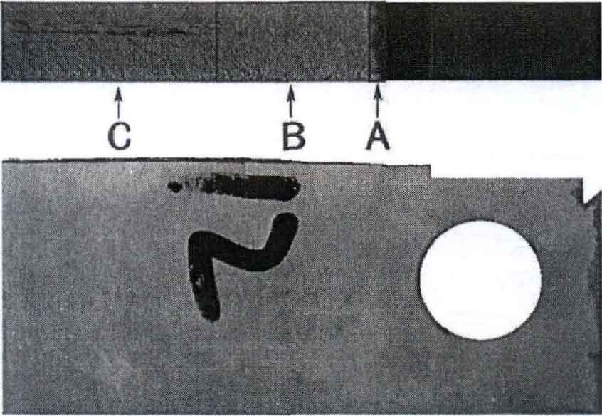
A is used to represent the fatigue source area (low-speed propagation stage); B represents the stable propagation region (stable propagation stage) and C represents the instantaneous fracture region (high-speed propagation stage). This corresponds to the three stages of fatigue crack growth shown in Figure 2 from the fatigue crack growth test.


The cross-section characteristics of fatigue fracture are composed of the above three regions. The crack source region accounts for a small proportion in the whole fracture, and the crack begins to sprout from this position. The crack source is located on the leftmost side of the fracture and extends slowly to the right. In the stage of slow crack growth, a smooth region will be formed, which appears in the bright region of the crack source, because the crack opening displacement is small and the fracture surfaces are constantly rubbing against each other. The characteristic of stable crack growth zone is that the section looks relatively smooth, and one third of the area of the section is the growth area, which is an important area to describe the characteristics of fatigue fracture.
The fracture surface of the sample is rubbed repeatedly, and the fracture surface becomes smooth and the microstructure is fine crystal. The instantaneous fracture zone is behind the stable expansion zone. The fatigue crack will be unstable during the propagation process. When it expands to the critical value, the instability will occur and form an instantaneous fracture area (metal fracture analysis). In this area, it can be clearly observed that the fracture becomes rough and presents an unstable state, with torn gullies and bulges. The opening direction points to the crack propagation direction and is perpendicular to the load direction.