
Gear mesh generation strategy is directly related to the calculation speed and accuracy. In order to determine the finite element mesh model optimized for the static transmission error analysis of hypoid gears, the mesh convergence analysis is performed below. The quasi double curved tooth is divided into three areas, as shown in Fig. 1, the tooth surface contact area, the tooth root part and the gear base. The tooth surface is the meshing part of the interaction between gears. The meshing strategy directly affects the contact footprint of gears and whether the contact of hypoid gears can be accurately simulated. The tooth root is the main part of the gear that bears the alternating load, and is the most deformed part of the gear. The deformation of the tooth root is different with different mesh division methods. The hypoid gear base supports the whole gear tooth. During the gear meshing process, the extrusion deformation of the tooth surface is first caused, then the deformation of the tooth root is caused, and then it is transmitted to the gear blank. Therefore, in the whole gear finite element model, the hypoid gear base mainly transmits the load, and the mesh can be relatively coarse.
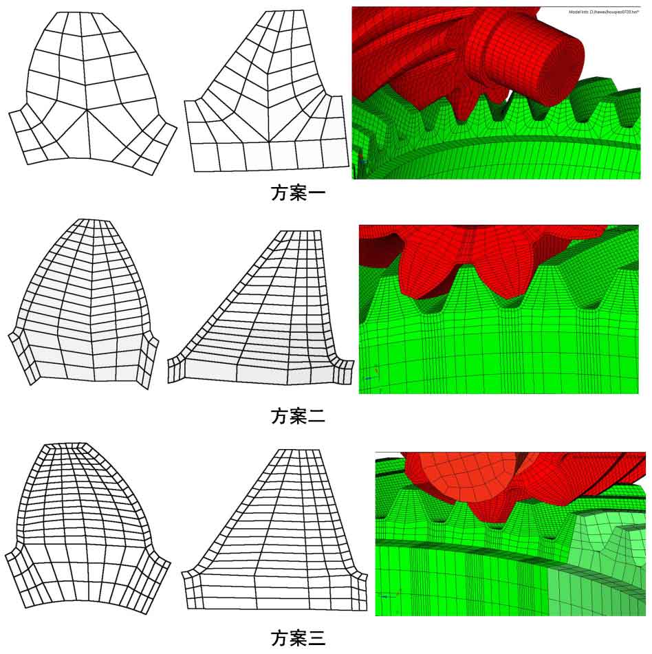
Three mesh generation strategies of hypoid gears are compared, as shown in Fig. 2. In scheme 1, the gear mesh generation strategy is adopted. In order to improve the contact condition of hypoid gears, the mesh at the contact tooth surface is refined in scheme 2. On the premise of ensuring that the mesh on the tooth surface is fine, the mesh in the middle of the gear blank is coarse, and the mesh at the tooth root is also refined. Compared with scheme 1, scheme 2 has improved the mesh of hypoid gears, but the number of meshes has increased a lot. The difference between scheme 3 and scheme 2 is that the large gears are divided into meshing parts and non meshing parts. In scheme 3, the meshing parts are relatively fine and the non meshing parts are relatively coarse. Similarly, the mesh of the hypoid gear shaft of small gears is relatively coarse, The mesh division of the hypoid gear tooth blank is relatively fine. Through simulation and comparative analysis of the meshes of the three schemes, the loading condition is that the load resistance moment of the large gear is 9000nm.
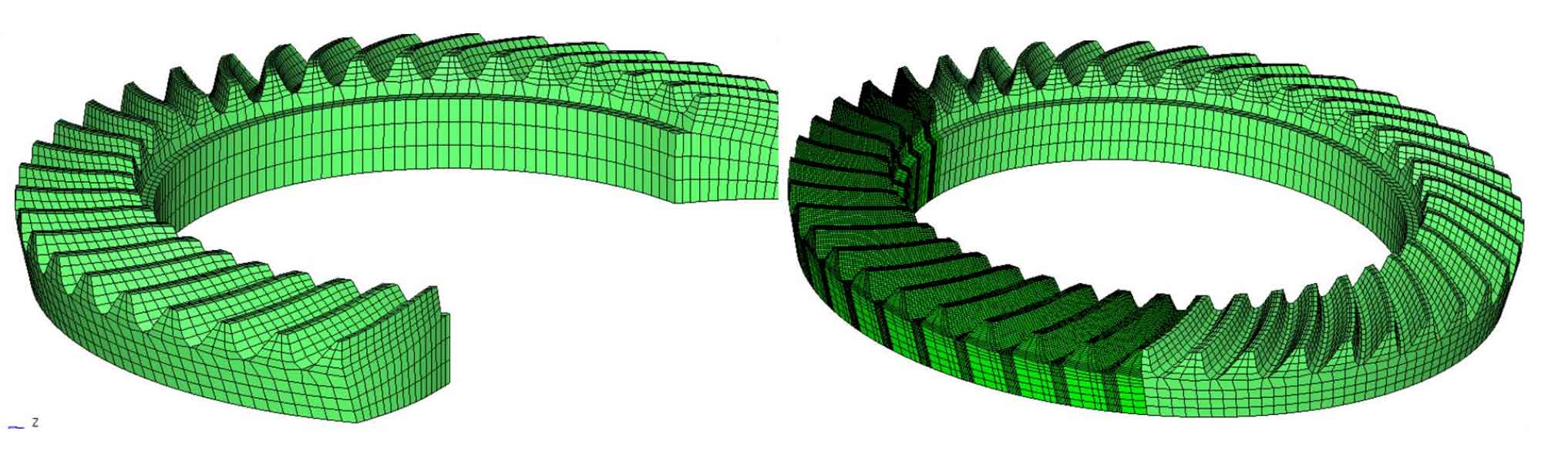
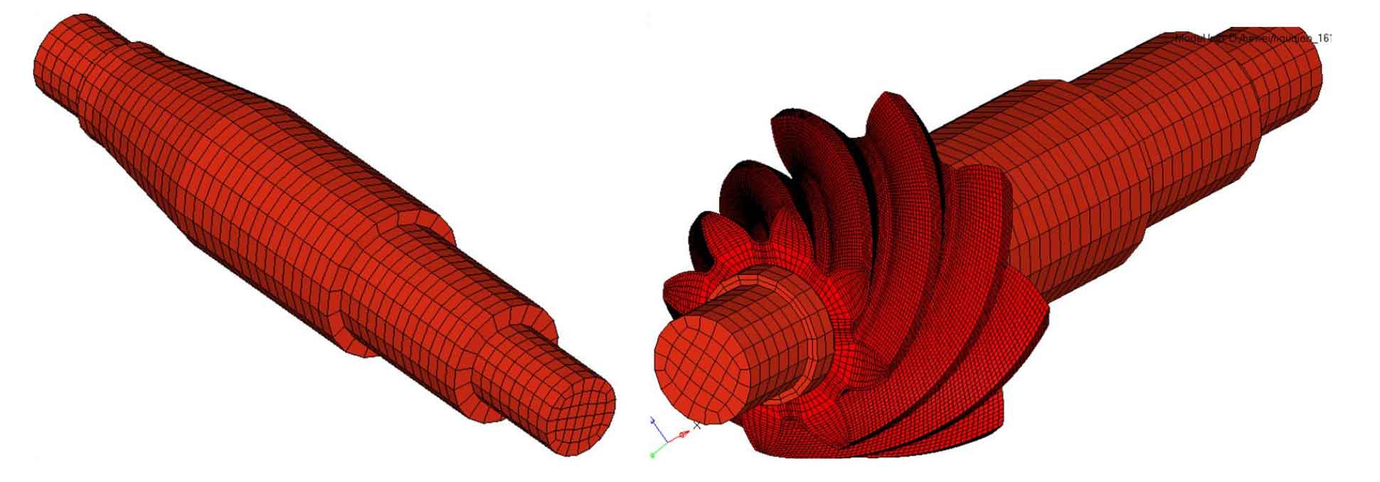
The table lists the maximum principal stress, peak value of transmission error and calculation time of tooth root calculated by different grids. The calculation results show that the calculation results of the latter two schemes are similar, but the calculation time of the third scheme is less than that of the second scheme. Therefore, the third scheme is selected for the calculation of transmission error. In order to reduce the calculation deviation caused by the simplification of the model and improve the calculation speed, the large and small gears are divided into meshing parts and non meshing parts, as shown in Fig. 3.
| Division method | Division method | Tooth surface (mm) | Tooth root (mm) | Gear blank (mm) | Maximum principal stress of tooth root (MPA) | Peak to peak value of transmission error (arcsec) | Computing time |
| Scheme I | Hypoid gear pinion | 5 | 2 | 5 | 930 | — | 3h |
| Scheme I | Hypoid gear wheel | 6 | 3 | 6 | 942 | 20 | |
| Scheme II | Hypoid gear pinion | 16 | 5 | 10 | 906 | — | 8h |
| Scheme II | Hypoid gear wheel | 16 | 6 | 13 | 915 | 17 | |
| Scheme III | Hypoid gear pinion | 15 | 5 | 15 | 902 | — | 4.5h |
| Scheme III | Hypoid gear wheel | 14 | 6 | 13 | 912 | 18 |