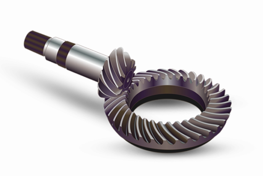
Spiral bevel gears (SBGs) are critical components in heavy-load transmission systems, yet they are prone to tooth root cracks under alternating stresses. Understanding the influence of crack types on meshing characteristics is essential for fault diagnosis and operational reliability. This study investigates the effects of planar and spatial cracks on the meshing stiffness, contact stress, and bending stress of SBGs using finite element analysis (FEA) and loaded tooth contact analysis (LTCA).

1. Mathematical Modeling of Spiral Bevel Gears
The tooth surface geometry of SBGs is derived from the machining coordinate system. The transformation matrix from the tool coordinate system \( O_j \) to the gear blank coordinate system \( O_i \) is expressed as:
$$ M_{ij} = M_{i,bi}M_{bi,ai}M_{ai,mi}M_{mi,ci}M_{ci,j} $$
where \( \psi_i \), \( \gamma_{mi} \), \( S_{ri} \), and other parameters define the relative positions between cutting tools and gear blanks. The tooth surface equation is derived using envelope theory:
$$ \mathbf{r}_i(s_j, \theta_j, \psi_i) = M_{ij}(\psi_i)\mathbf{r}_j(s_j, \theta_j) $$
$$ f_{ij}(s_j, \theta_j, \psi_i) = \left( \frac{\partial \mathbf{r}_i}{\partial s_j} \times \frac{\partial \mathbf{r}_i}{\partial \theta_j} \right) \cdot \frac{\partial \mathbf{r}_i}{\partial \psi_i} = 0 $$
2. Crack Modeling Methodology
Two crack types are investigated:
| Crack Type | Parameters | Description |
|---|---|---|
| Planar Crack | \( W \) (width), \( P \) (depth) | Propagates along tooth width and thickness |
| Spatial Crack | \( \alpha_1, \alpha_2, \alpha_3 \) (angles), \( S \) (depth) | 3D propagation from root to tip |
Crack implementation uses node replacement technique in FEA:
$$ \text{Modified Stiffness Matrix: } \mathbf{K}’ = \mathbf{K} – \sum_{e \in \Omega} \mathbf{K}_e + \sum_{e \in \Omega’} \mathbf{K}_e’ $$
where \( \Omega \) and \( \Omega’ \) represent original and modified element sets.
3. Meshing Stiffness Calculation
Time-varying meshing stiffness \( k(t) \) is calculated as:
$$ k = \frac{F}{E} = \frac{T}{R \sin \delta_{A1} \cos \alpha_n \cos \beta} \cdot \frac{1}{\theta R \sin \delta_{A1} \cos \alpha_t \cos \beta_b} $$
Key parameters include:
| Symbol | Description | Value |
|---|---|---|
| \( T \) | Torque | 120 N·m |
| \( R \) | Mid-point cone distance | 85 mm |
| \( \delta_{A1} \) | Pinion pitch angle | 25° |
4. Results and Discussion
4.1 Meshing Stiffness Reduction
| Crack Type | Maximum Stiffness Reduction | Critical Engagement Phase |
|---|---|---|
| Planar Crack | 27.58% | Contact ellipse over crack zone |
| Spatial Crack | 14.12% | Partial crack engagement |
| Tooth Breakage | 32.82% | Complete tooth separation |
4.2 Stress Distribution Characteristics
Bending stress \( \sigma_b \) and contact stress \( \sigma_c \) follow:
$$ \sigma_b = \frac{6Fh}{bt^2} \left( 1 – \frac{a}{t} \right)^{-\frac{3}{2}} $$
$$ \sigma_c = \sqrt{\frac{F}{\pi b} \left( \frac{1-\nu_1^2}{E_1} + \frac{1-\nu_2^2}{E_2} \right)^{-1}} $$
Key observations include:
- Planar cracks increase root stress concentration by 18-47%
- Spatial cracks reduce effective contact area by 9-15%
5. Conclusion
The study establishes quantitative relationships between crack parameters and meshing characteristics in spiral bevel gears. Planar cracks demonstrate greater stiffness reduction (27.58%) compared to spatial cracks (14.12%), while tooth breakage causes the most severe degradation (32.82%). The proposed node replacement method effectively simulates crack propagation effects, providing theoretical support for condition monitoring of spiral bevel gear transmission systems.
