Abstract:
This paper presents an analysis of the meshing characteristics of hypoid gears with extended epicycloid, focusing on contact patterns, bending stresses, contact ratios, and transmission errors. The results are summarized using tables and visual aids to enhance readability.

1. Introduction
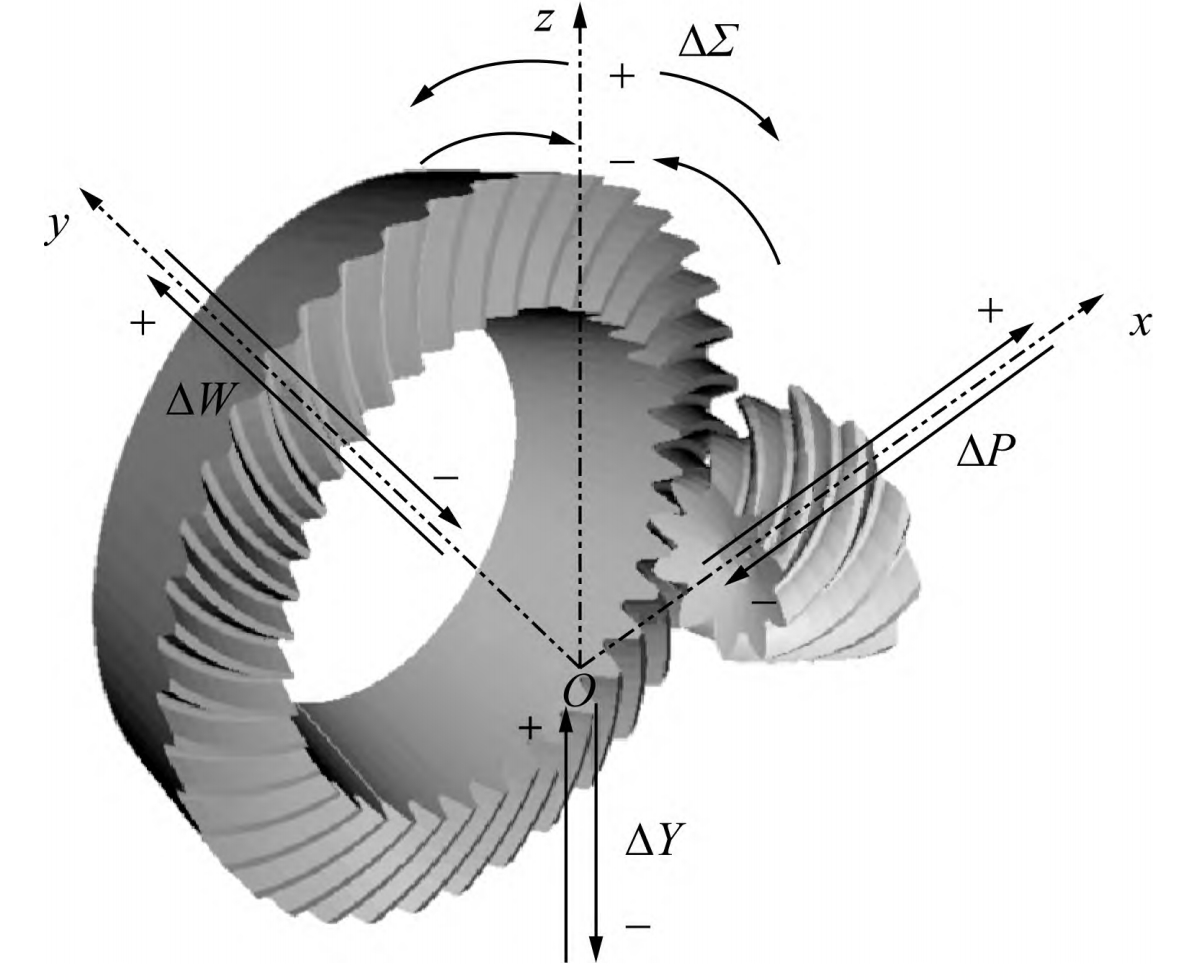
Hypoid gears are widely used in automotive drive axle final drives due to their high contact ratio, smooth transmission, and strong carrying capacity. The meshing excitation of hypoid gears is a major source of vibration and noise in drive axles, necessitating a study of their meshing characteristics.
Table 1: Types of Hypoid Gears
| Type | Description | Characteristics |
|---|---|---|
| Gleason Gear | Arc tooth hypoid gear | Gradually reducing tooth height; increasing root cone angle, face cone angle, and pitch cone angle |
| Oerlikon Gear (Extended Epicycloid) | Constant tooth height hypoid gear | Equal root cone angle, face cone angle, and pitch cone angle; high production efficiency, low cost, and low noise |
2. Finite Element Modeling of Hypoid Gears
The finite element model of the hypoid gears was established using HyperMesh and ABAQUS software.
Table 2: Modeling Steps
| Step | Description |
|---|---|
| Mesh Generation | Hexahedral elements with a Jacobian coefficient greater than 0.7 |
| Material Property Definition | Setting material properties, boundary conditions, loads, and analysis steps |
| Tooth Contact Settings | Using the implicit solver in ABAQUS; “surface to surface” contact method |
3. Contact Patterns on Tooth Surfaces
Table 3: Contact Pattern Characteristics
| Direction of Meshing | Contact Surfaces | Contact Pattern Shape | Contact Area Variation |
|---|---|---|---|
| Forward | Concave surface of pinion and convex surface of gear | Approximately oval | Increases first and then decreases |
| Reverse | Convex surface of pinion and concave surface of gear | Approximately oval | Opposite direction of meshing entry and exit |
4. Bending Stresses at Tooth Roots
Table 4: Stress Characteristics at Danger Points
| Gear Type | Stress Type | Stress Variation with Pinion Rotation |
|---|---|---|
| Pinion | Tensile stress first, then compressive stress | – |
| Gear | Compressive stress first, then tensile stress | – |
5. Contact Ratio
The contact ratio is a crucial indicator of gear carrying capacity and transmission smoothness.
Table 5: Contact Ratio Characteristics
| Load | Contact Ratio (ε) | Variation Trend |
|---|---|---|
| Near 0 Nm | 1 | – |
| Increasing load | Gradually increases | Faster increase at low loads; slower increase at high loads |
| Maximum observed | ~2.5 | – |
6. Transmission Error
Definition: Transmission error is the deviation between the actual angle of rotation of the driven gear and the theoretical angle of rotation of the driving gear.
Table 6: Transmission Error Characteristics
| Load | Transmission Error Amplitude Variation |
|---|---|
| Small loads | Large amplitude; fluctuates significantly |
| Increasing load | Amplitude decreases; transmission becomes smoother |
| Critical low load | Minimum amplitude point |
| Critical high load | Maximum amplitude point; then gradually decreases and stabilizes |
7. Experimental Validation
Field tests were conducted to validate the simulation results.
Table 7: Experimental Results Summary
| Test Condition | Observation |
|---|---|
| Lubricant temperature | Had minimal impact on transmission error |
| Comparison with simulations | Consistent trends and amplitudes; validated finite element model |
8. Conclusions
- The contact area on the tooth surface is approximately oval and varies during meshing.
- Danger points at tooth roots experience predominantly tensile and compressive stresses, with different variation patterns for pinions and gears.
- The contact ratio increases with load, enhancing gear carrying capacity and transmission smoothness.
- Transmission error is significantly affected by load, with amplitude variations following a specific trend.
This comprehensive analysis provides valuable insights for the design and use of hypoid gears with extended epicycloid, contributing to the advancement of automotive drive axle technology.
